Microparticulate feeder for larval and juvenile fishes

a technology of microparticulate and fish, which is applied in the field of fish feeders, can solve the problems of reducing the quality of feed, reducing the number of components, and reducing the efficiency of feeding, so as to reduce the cost and complexity of the device, reduce the number of components, and avoid moisture and caking

a technology of microparticulate and fish, which is applied in the field of fish feeders, can solve the problems of reducing the quality of feed, reducing the number of components, and reducing the efficiency of feeding, so as to reduce the cost and complexity of the device, reduce the number of components, and avoid moisture and caking

US9113615B1Active Publication Date: 2015-08-25THE UNITED STATES OF AMERICA AS REPRESENTED BY THE SECRETARY OF THE COMMERCE

Image

  • Microparticulate feeder for larval and juvenile fishes
  • Microparticulate feeder for larval and juvenile fishes
  • Microparticulate feeder for larval and juvenile fishes

Examples


Embodiment Construction

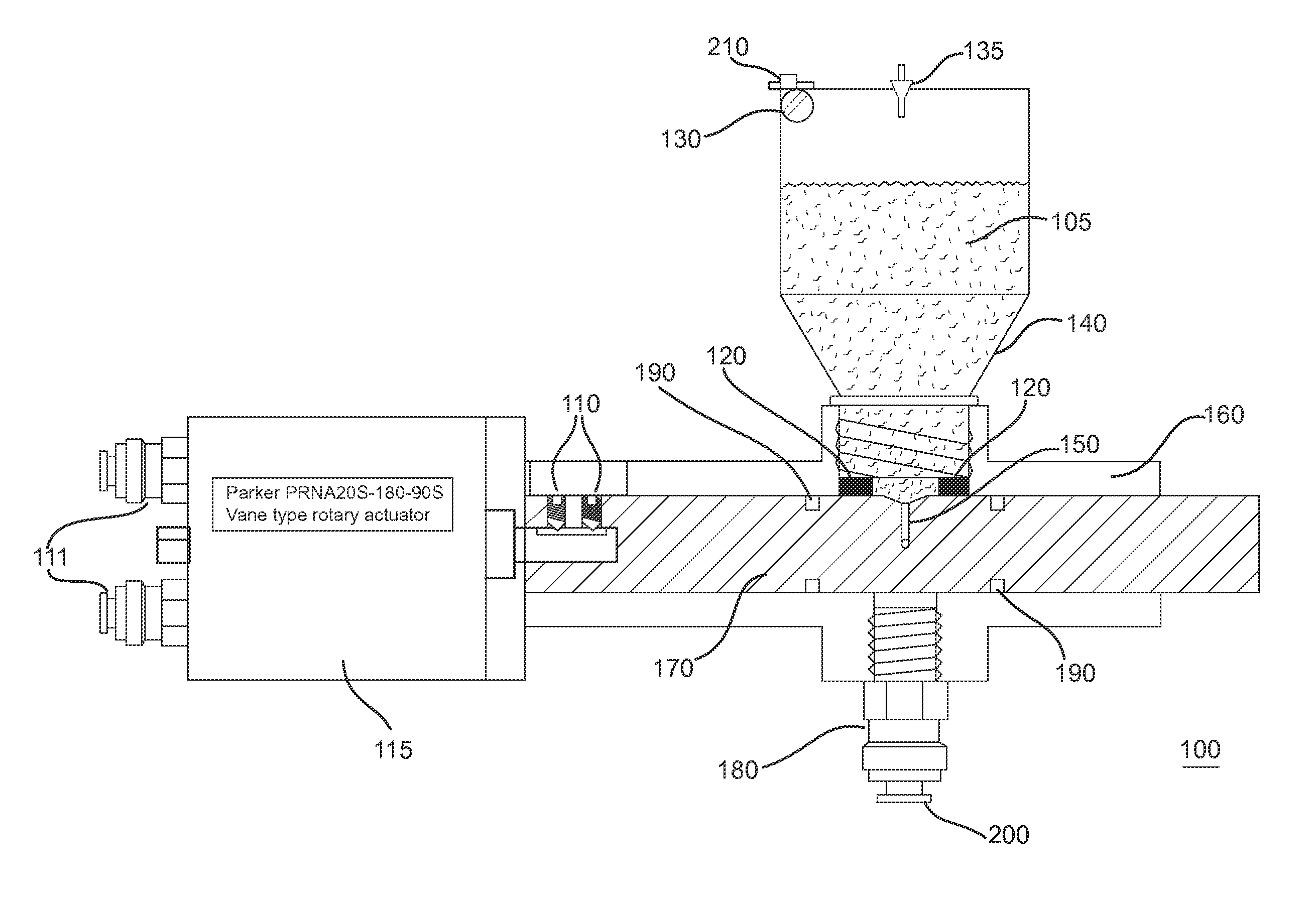
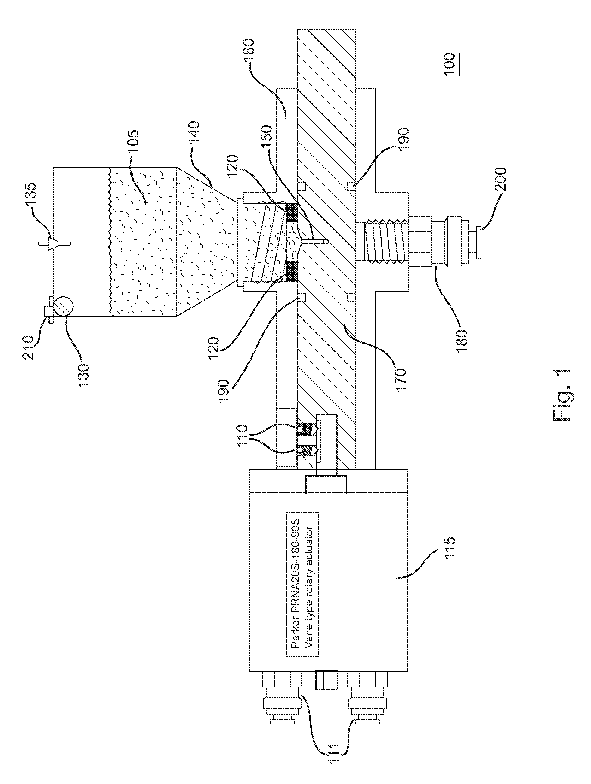
[0041]FIG. 1 is an elevation view of dispenser components of microparticulate feeder. Note that the depicted design uses ‘O’ rings 190 as both seals and bearings. In an alternative embodiment, captive ball bearings and cup seals may be used to ensure long-term performance over a heavy-duty cycle.

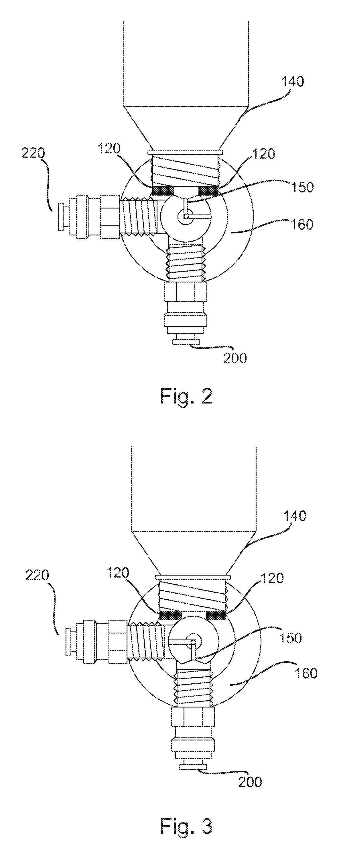
[0042]Referring to FIG. 1, the feeder of the present invention uses a manifold delivery system (as shown in FIG. 4) attached to a central dispensing unit 100. Thus, one feeder can feed several fish tanks. The feeder 100 dispenses a discrete volume of feed 105, determined by a chamber 150 in a rotating shaft 170, rotating within housing 160. The feed 105 is loaded into the chamber 170 by gravity from a sealed hopper 140 above the chamber 150. A small vibrator 130, attached to the hopper 140, aids in settling the feed into the chamber. Vibrator 140 may comprise a cell phone type vibrator commonly known in the cell phone art. The chamber 150 includes an L-shaped airway radially situated through...


PUM


Abstract

A feeder for larval and juvenile fishes is capable of delivering a small (ca. 15 mg) precise dose of microparticulate (ca. 100 μm diameter) feed to selected locations, via pneumatic conveyance and control. A source of low-pressure dry gas is used to blow microparticulate feed through a manifold and into a selected one of a number of tubes. A terminal valve at the end of the tube is selectively activated to send the feed to a selected tank or pond. When not in use, the feeder is sealed, and the feed protected from moisture and ambient oxygen.

Description

STATEMENT OF GOVERNMENT INTEREST[0001]The research that led to the development of the present invention was sponsored by the National Oceanic and Atmospheric Administration's (NOAA's) National Marine Fisheries Service (NMFS). NOAA is a part of the U.S. Department of Commerce, a component of the U.S. Federal government. The United States Government has certain rights in this invention.FIELD OF THE INVENTION[0002]The present invention relates to fish feeder. In particular, the present invention is directed toward a microparticulate feeder for larval and juvenile fishes.BACKGROUND OF THE INVENTION[0003]Microparticulate diets for larval and small juvenile fish pose specific challenges for aquaculturists. Microparticulate diets, by definition, have a very high specific surface area, making them vulnerable to the effects of oxidation and hydration. Many of the diet components are often labile and hygroscopic, which further exacerbates the problem. Fine, hygroscopic particles tend to clump...

Claims


Application Information

Patent Timeline
25 Aug 2015
Publication
US9113615B1
IPC
A01K61/02; A01K5/02
CPC
A01K61/02; A01K61/025; A01K5/0291; A01K5/0275; A01K61/85; A01K61/80; Y02A40/81
Inventors
SCOTT, THOMAS M; WEBB, JR., KENNETH ASHLEY