Rotary drill

a rotary drill and drill bit technology, applied in drilling machines, turning apparatuses, cutting machines and methods, etc., can solve the problems of too sharp cutting edge and dead center, and achieve the effect of reducing thrust load, less wear, and long li

Active Publication Date: 2015-09-15
BAUER DRILL
View PDF12 Cites 0 Cited by
  • Summary
  • Abstract
  • Description
  • Claims
  • Application Information

AI Technical Summary

Benefits of technology

[0022]The rotary masonry drill or drill bit is adapted for drilling in porous materials, for instance selected from the group consisting of tiles, bricks, masonry, concrete, granite, repair mortar, artificial granite, breeze block, capping stone, concrete, hardened roof tiles, marble and ceramic materials. The drill is not limited to use in drilling in these materials, and may be used in connection with any other materials used in for instance masonry construction, including marble, granite, travertine, limestone, or brittle materials, such as glass, etc. The groove may be provided in drills for drilling in a large variety of materials; however, it has proved to be of a particular advantage in terms of its ability to increase the drilling rate and in terms of extending the lifespan of the drill / drill bit due to less wear and tear. When in use, it is important not to use the drill as a hammer drill. Otherwise, the effect of the invention will not be obtained and may have detrimental effect on the drill / drill bit itself. Thus, the drilling machine should perform a rotation of the drill only with no pulsating axial movement thereof. As a consequence, it has turned out to be possible to drill in materials, in which the drilling in the prior art has hitherto only been possible by the use of the hammer function. By avoiding the hammer function, the disadvantages of vibrations, white fingers and noise is avoided. As a further consequence, it has turned out be possible to drill a clean-cut hole in ceramic materials as well as in glass material.
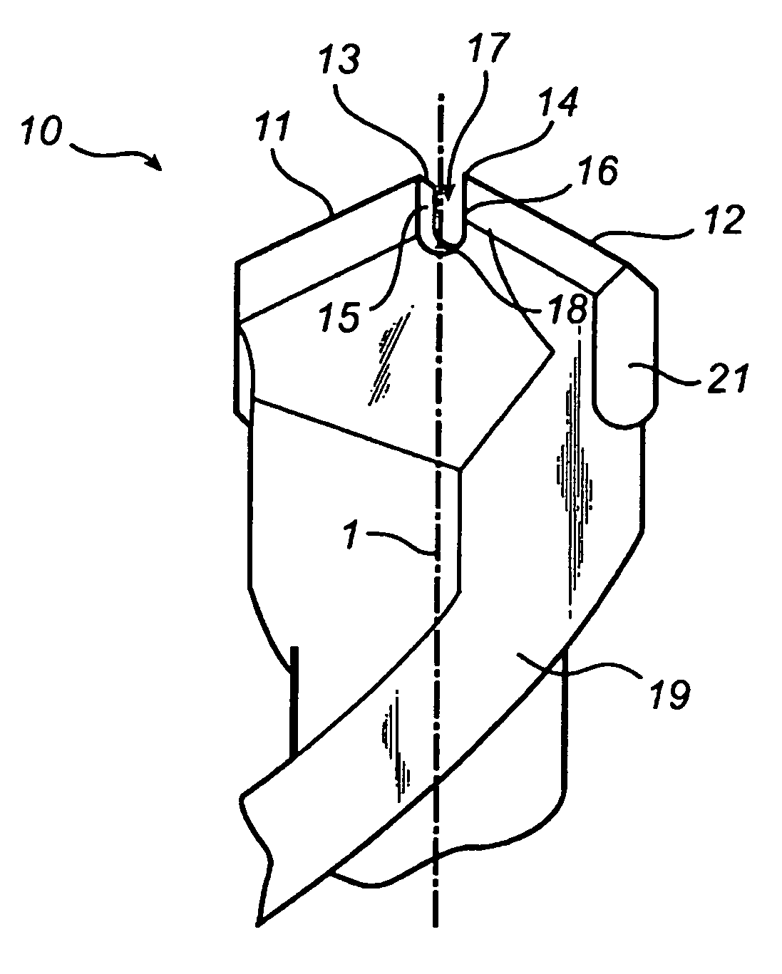
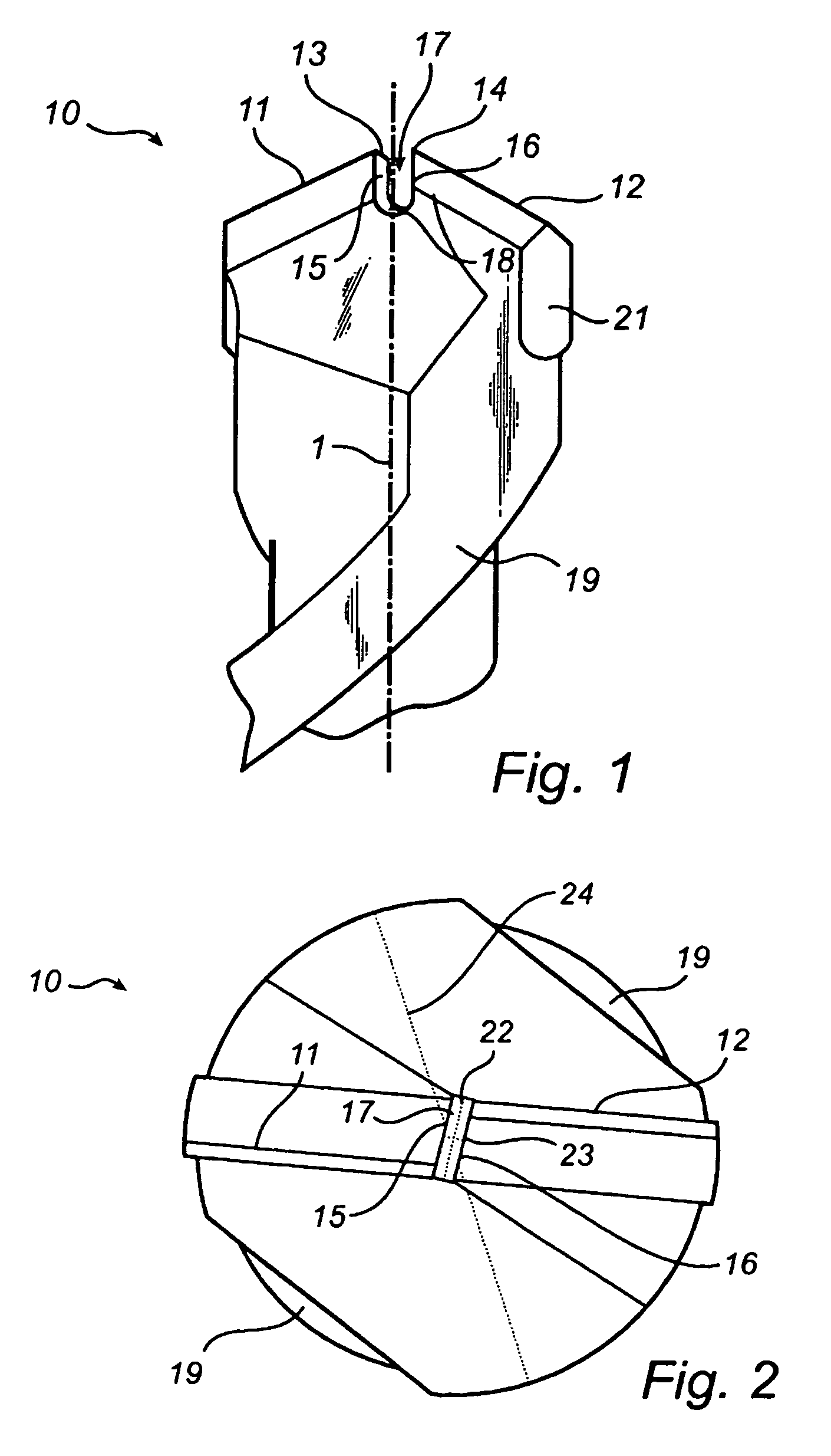
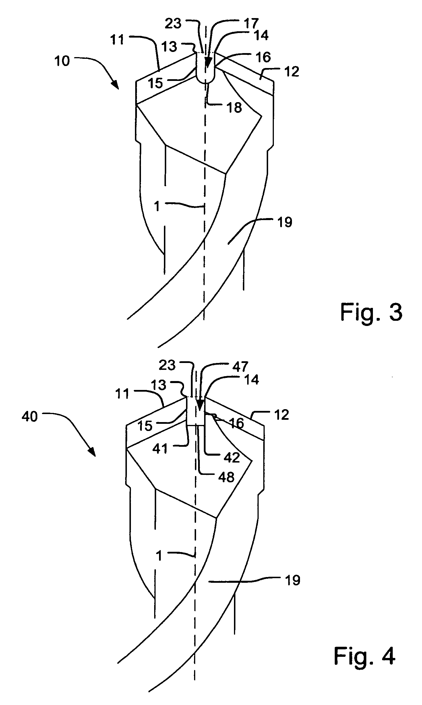
[0023]In an embodiment of the invention the left side and the right side of the groove are parallel to each other or form an angle of less than 30 degrees relative to each other. Such angles, for instance less than 20 degrees or essentially parallel to the axis of rotation of the drill, and thereby creating a sharper angle, the area where no cutting is taking place is limited, and thus a reduced thrust load is required to remove the material from the dead center and hence, the cutting edges are exposed to less wear. The angle may also be less than 0 degrees, meaning the groove is wider at the bottom than between the two end points.
[0024]The drill or the drill bit may comprise three or four cutting edges. By having more than two cutting edges the wear will be distributed over more cutting edges and the drill will have a longer life. The three or four cutting edges may be either outer cutting edges or inner cutting edges or a combination there of.
[0025]The distance between the two end points may be smaller than a length of a bottom of the groove. This provides the drill or the drill bit with a greater resistance to breaking.
[0026]The diameter of the rotary drill may also be equal to or smaller than 9 mm, 8 mm, 6 mm, 5 mm or 4 mm. In particular with a diameter of 9 mm or less, a relative greater improvement in the drilling rate was seen than with the larger drills or drill bits. The diameter of the rotary drill or drill bits may also be equal to or greater than 5 mm, 6 mm, or 8 mm. Thus, in a certain embodiment of the present invention, the drill diameter is in the range of 5.0 mm to 9.0 mm and the groove width is in the range of 1.0 mm to 1.5 mm. To obtain the fastest drilling rate and at the same time an easy centering of the drill it is preferred that the diameter of the rotary drill is in the range of 6.0 mm to 9.0 mm and the groove width is in the range of 1.1 mm to 1.4 mm.
[0027]In another embodiment of the invention the diameter of the rotary drill may be equal to or greater than 15 mm, 16 mm, 18 mm, 20 mm, 22 mm, 24 mm, 26 mm, 28 mm, and 30 mm. The groove width is suitably in the range of 1.0 to 1.5 mm, preferably in the range of 1.1 to 1.4 mm for obtaining a fast drilling rate as well as an easy centering of the rotary drill. The groove may be deeper than it is wide. By having this relationship between the groove depth and the groove width the drill cuttings or drill column accumulated in the dead center has a greater room where it can work before it is either crushed against the bottom or turned into dust or ground by the forces perpendicular to the axis of rotation. Consequently the drill meets less resistance and less thrust load or forces perpendicular to the axis is required.

Problems solved by technology

An angle close to 0 will provide the sharpest cutting; however, in some applications the cutting edge will be experienced as “too sharp” and might entail that the drill is stuck in the material.
This is very different from a traditional drill / drill bit having a tip only, giving rise to a dead center.

Method used


Image

  • Rotary drill
  • Rotary drill
  • Rotary drill

Examples


example 1

[0134]An 8 mm Irwin® 10501934 drill was mounted in a pillar drill. The pillar drill was loaded with a constant pressure of 10 kg and rested on a brick. The drilling machine was started and allowed to drill in the brick for the time period indicated in the table.

[0135]

TABLE 1Groove width / mmDrilling depth / mmTime / sec0 (no groove)14200.723201.231201.52920

[0136]Example 1 shows a significantly improved drilling rate as the drill depth is more than doubled, when a groove width of 1.2 mm or 1.5 mm is provided in comparison to when no groove is provided. The drilling rate is significantly improved where a groove width of 0.7 mm is provided. The best result achieved for an 8 mm drill bit is where a groove width of 1.2 mm is provided, corresponding to an increase in drilling rate of 121%.

example 2

[0137]A 16 mm Irwin® 10501867 drill was mounted in a pillar drill. The pillar drill was loaded with a constant pressure of 10 kg and rested on a brick. The drilling machine was started and allowed to drill in the brick for the time period indicated in the table.

[0138]

TABLE 2Groove width / mmDrilling depth / mmTime / sec0 (no groove)7.9401.29.240

[0139]Example 2 shows that the drilling depth has been increased by 1.3 mm, which is an improvement of 16.5% over a drill bit with no groove. Hence, a groove width of 1.2 mm is preferred over no groove.

example 3

[0140]A 6 mm Irwin® drill was mounted in a pillar drill. The pillar drill was loaded with a constant pressure of 10 kg and rested on a brick. The drilling machine was started and allowed to drill in the brick for the time period indicated in the table.

[0141]

TABLE 3Groove width / mmDrilling depth / mmTime / sec0 (no groove)20.8201.033.4201.237.920

[0142]Example 3 shows a significant improvement in the drilling rate when providing the drill bit with a groove width of 1.0 or 1.2 mm, in comparison to when no groove is provided.


PUM

PropertyMeasurementUnit
diameteraaaaaaaaaa
diameteraaaaaaaaaa
diameteraaaaaaaaaa

Abstract

In a rotary drill, the drill is provided with at least one groove, which has a center lying on the axis of rotation of the drill. The two end points of the groove define a groove width, and the drill is provided with two or more cutting edges. Two cutting angles are defined. The groove has a left side and a right side. The rotary drill can be used in a rotary drilling machine. The drill can be provided with a drill bit.

Description

CROSS-REFERENCE TO RELATED APPLICATIONS[0001]This is a national stage of PCT / DK10 / 000154 filed Nov. 24, 2010 and published in English, claiming the priority of Denmark number PA 2009 70242 filed Dec. 3, 2009, and claiming the benefit of U.S. provisional application No. 61 / 326,382, filed Apr. 21, 2010, hereby incorporated by reference.BACKGROUND OF THE INVENTION[0002]1. Field of Invention[0003]The present invention relates to a rotary masonry drill, wherein the drill is provided with at least one groove, of which one groove has a center lying on the axis of rotation of the drill, each said at least one groove extending between two end points defining a groove width, the drill comprises at least two cutting edges, each cutting edge defining a respective cutting angle, the groove comprising a left side and a right side, wherein the groove width is between 0.6 mm and 1.8 mm and the rotary drill has a diameter between 2 mm and 45 mm, and each cutting angle is between 30 and −30 degrees i...

Claims


Application Information

Patent Timeline
Patent Type & Authority Patents(United States)
IPC IPC(8): E21B10/44B28D1/14B23B51/02
CPCB28D1/146B23B51/02E21B10/44B23B2226/75B23B2251/18B23B2251/46
Inventor BAUER, KIM
Owner BAUER DRILL
Why Eureka
Try Eureka