Method and device for the treatment of waste water

a technology for waste water and treatment methods, applied in biological water/sewage treatment, water/sludge/sewage treatment, chemical instruments and processes, etc., can solve the problems of unfavorable purification efficiency, high energy requirements, and high oxygen requirements, and achieve the effect of reducing the risk of undesired growth in pipes

Active Publication Date: 2015-09-15
BIOWATER TECH AS
View PDF23 Cites 5 Cited by
  • Summary
  • Abstract
  • Description
  • Claims
  • Application Information

AI Technical Summary

Benefits of technology

[0031]A first advantage of the invention is mainly to treating water both under anoxic / anaerobic conditions and under aerobic conditions within a single reactor volume. A large proportion of the suspended solids in the feed water and the effluent will be removed biologically and hydrodynamically. In the present invention, the biological material produced in the upper, aerobic zone is allowed to become exposed for the lower, anaerobic / anoxic zone and thus reduces the amount of total aerobic sludge mass produced, as opposed to the devices of the background art where organic matter produced in the aerobic zone is prevented from falling down into the anoxic / anaerobic zone. In the present invention, the biological material produced in the upper, aerobic zone is allowed to become exposed to the lower, anaerobic / anoxic zone and thus reduces the total sludge mass produced. A very large proportion of biomass grown in the aerobic zone is conducted down to be reprocessed in the anaerobic / anoxic zone, eventually producing sludge waste.
[0032]A second advantage of the invention is a more efficient decomposition of organic compounds from the feed water, that results in reduced amount of sludge waste produced and thus reduced pollution to the environment. This will result in less clogging problems within the reactor, thus reducing the need for post treatment of sludge disposal such as conventional sludge dewatering, conventional sludge stabilizer, chemical disinfection or other post-treatment techniques.
[0033]A third advantage of the invention over the background art, is the eventual removal of sludge occurs from the anaerobic / anoxic zone, which disposes of the need to remove sludge from the upper, aerobic zone.
[0034]A fourth advantage of the invention is to mainly reducing inorganic and organic chemicals, and solid particles in the treated water, reducing the risk of eutrophication in the recipient.
[0035]A fifth advantage of the invention is that the residence time of the sludge in the anaerobic / anoxic reaction zone is increased, and thus more time is available for gravitational compression and stabilization of the sludge, such that the resulting sludge volume is reduced.
[0036]A sixth advantage of the invention is a reduced requirement of oxygen and thus a reduced need for energy consumption for pumping air to the bubble diffuser to release oxygen bubbles to below the aerobic zone.

Problems solved by technology

1, lines 47-50: “As the result of the fact that the flow in the aerobic reactor may be fairly turbulent, the anaerobic biomass cannot sink back into the anaerobic reactor, which adversely affects the purification efficiency”.
As the two zones are separated, and the aerobic zone is not pure, much oxygen is required, which requires much energy.
There is a general risk of undesired growth in pipes.
A disadvantage of the background art among other factors is the production of suspended solids and other chemicals.
Such components may incur undesired eutrophication.
A major drawback to U.S. Pat. No. 6,132,602 is firstly that the finely distributed biological material will not easily settle into the sludge zone.
Furthermore, even a second settling zone will not adequately remove all suspended solids, and further treatment of the effluent will be needed.
Such a design further presents the disadvantage of having to bubble a large amount of air through the system, thus being energy intensive.
Moreover, U.S. Pat. No. 6,132,602 calls for installing a number of disc elements and channels into the reactor space, thus both increasing capital expenditure, and reducing the available reactor volume.
Furthermore, this reactor functions according to the air lift method, and is thus rather energy intensive.
The effluent will also comprise quite a large amount of suspended solids due to the violent agitation of the wastewater.

Method used


Image

  • Method and device for the treatment of waste water
  • Method and device for the treatment of waste water
  • Method and device for the treatment of waste water

Examples


Embodiment Construction

[0050]The invention will be described with reference to the attached figures the scope of the invention being solely limited by the enclosed claims.

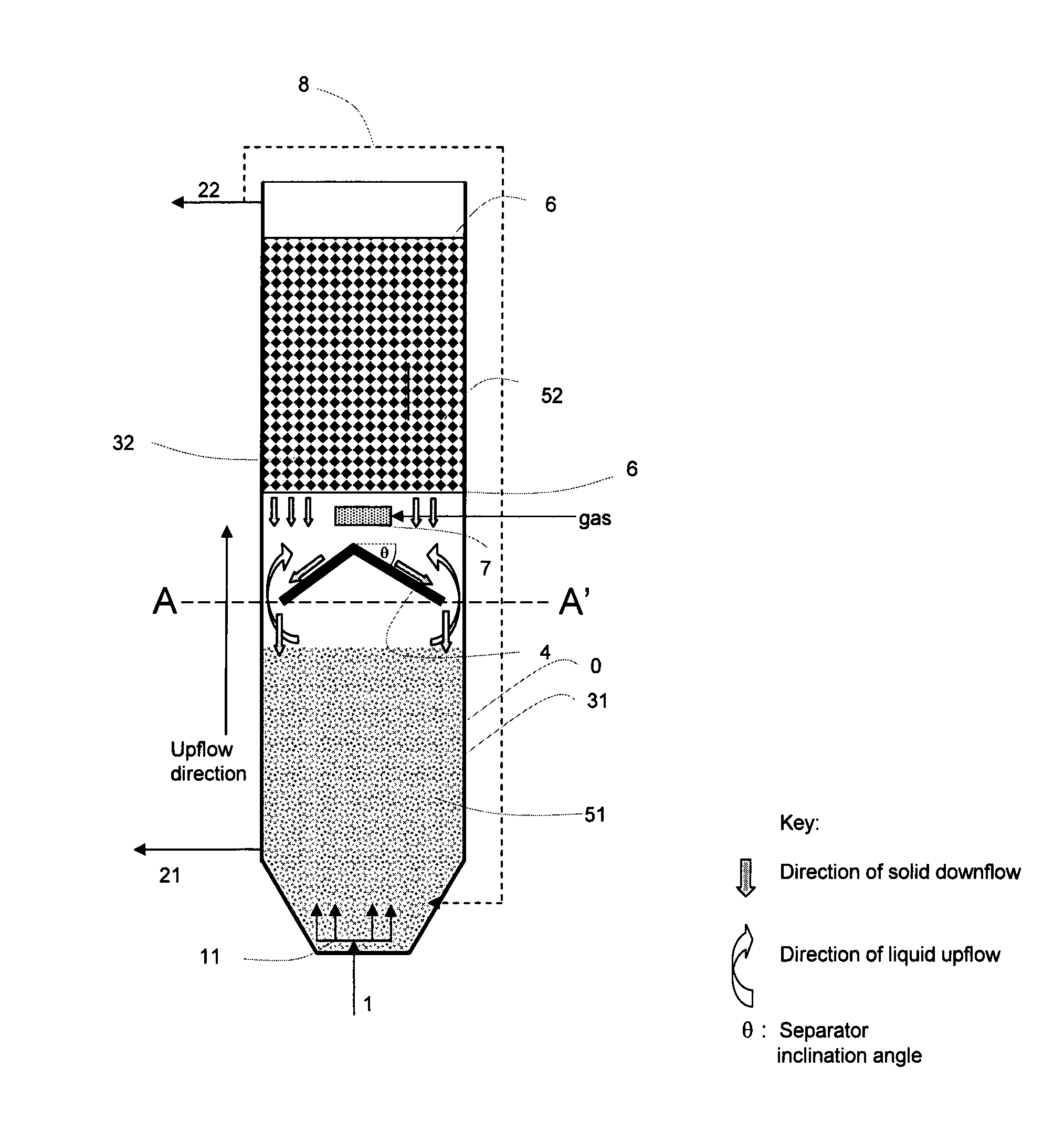
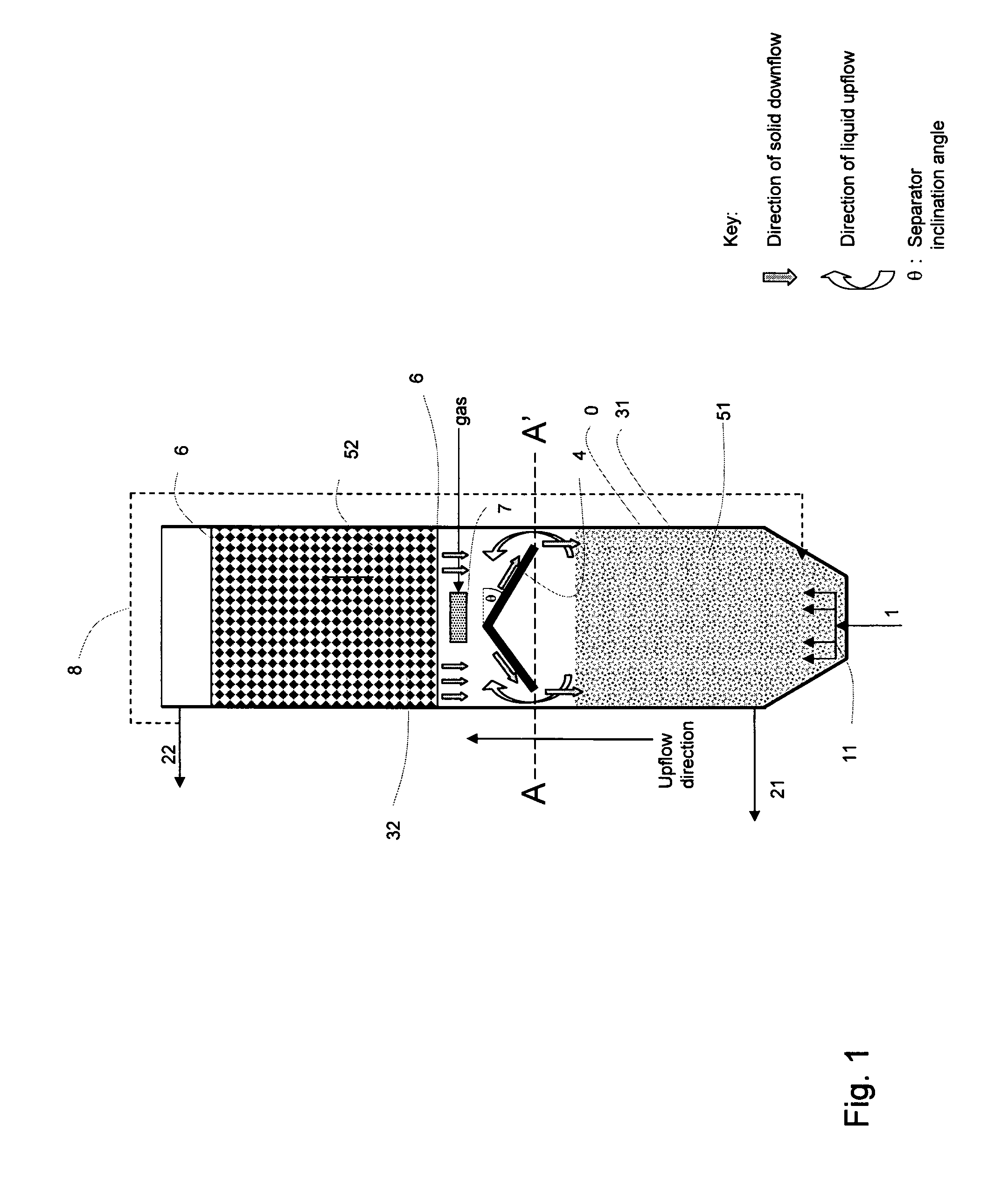
[0051]The present invention presents a reactor wherein the reactor volume allows an anoxic / anaerobic treatment as well as an anaerobic treatment of feedwater to take place within said volume. The reactor tank (0) comprises inlets for the feedwater (1) to be treated, and outlets for effluent (22) and sludge (21). The inlets (1) for feedwater should be arranged at the lower end of the reactor tank (0) such that the feedwater passes through the sludge or possible biofilm media (51) arranged therein. This is an advantage as the feedwater will provide carbon to the anoxic / anaerobic reaction zone (31). The feedwater will as a consequence first be treated within the lower anoxic / anaerobic reaction zone (31).

[0052]In an embodiment of the invention the feedwater is distributed through a feedwater flow distributor (11) such that the feedwater flow...


PUM

PropertyMeasurementUnit
velocityaaaaaaaaaa
angleaaaaaaaaaa
velocitiesaaaaaaaaaa

Abstract

The invention relates to a reactor for treatment of waste water for being subject to both anoxic / anaerobic and aerobic treatment within one single reactor volume. The anoxic / anaerobic reaction zone is separated from the aerobic reaction zone by a separator which also works as a hydrodynamic separator between the two reaction zones. The reactor makes it possible that the effluent water has a lower proportion of suspended solids and also that it produces less sludge than reactors of comparison. The reactor is further more energy efficient than prior art reactors. Several reactors according to the invention may be arranged in parallel so as for the inlet waste water may be treated in a modular way, and thus allowing the maintenance of the units to be facilitated.

Description

INTRODUCTION[0001]The present invention relates to a method for treating wastewater wherein the wastewater is arranged for being treated in a single reactor generally comprised of two reaction zones. The reactor is arranged for treating water both anoxially / anaerobically and aerobically within a single reactor volume. According to the invention the reactor is particularly well-adapted for treating industrial, municipal, agricultural or other wastewater. This entails that preferably a large proportion of the suspended solids should be removed from the feed-water, as well as removing as much as possible of any biological material in the treated effluent from the reactor. The reactor according to the invention is arranged for reducing a suspended solid in the treated effluent from the reactor and thus reducing the need of post treatment processes of the effluent such as physical / chemical sedimentations, reducing a water consumption for cleaning the reactor and the post treatment proces...

Claims


Application Information

Patent Timeline
Patent Type & Authority Patents(United States)
IPC IPC(8): C02F3/30
CPCC02F3/301Y02W10/10C02F3/06C02F3/30
Inventor PHATTARANAWIK, JIRACHOTELEIKNES, TOR OVE
Owner BIOWATER TECH AS
Why Eureka
Try Eureka