System and method for de-gassing and neutralizing equipment

Active Publication Date: 2015-09-22
HAFFNER KENNETH +1
View PDF8 Cites 4 Cited by
  • Summary
  • Abstract
  • Description
  • Claims
  • Application Information

AI Technical Summary

Benefits of technology

[0006]The present invention is directed to a system and method for de-gassing, decontaminating, and neutralizing various components of manufacturing units, such as refining units within a petrochemical refinery or other facility includi

Problems solved by technology

While these new energy industries attempt to reduce the need for conventional fuels such as petroleum, coal, and natural gas, these new energy industries are simply not able to produce the energy needed by modern day society.
Turnarounds are very expensive because of the lost production while a process unit is offline and due to the costs of tools, heavy equipment, materials, labor, and other expenses incurred in successfully executing a turnaround and performing much needed maintenance to th

Method used


Image

  • System and method for de-gassing and neutralizing equipment
  • System and method for de-gassing and neutralizing equipment

Examples


Example

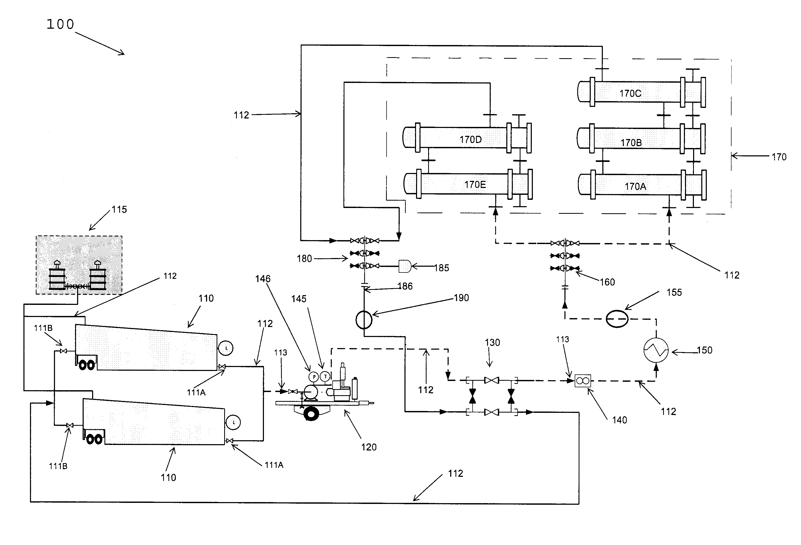
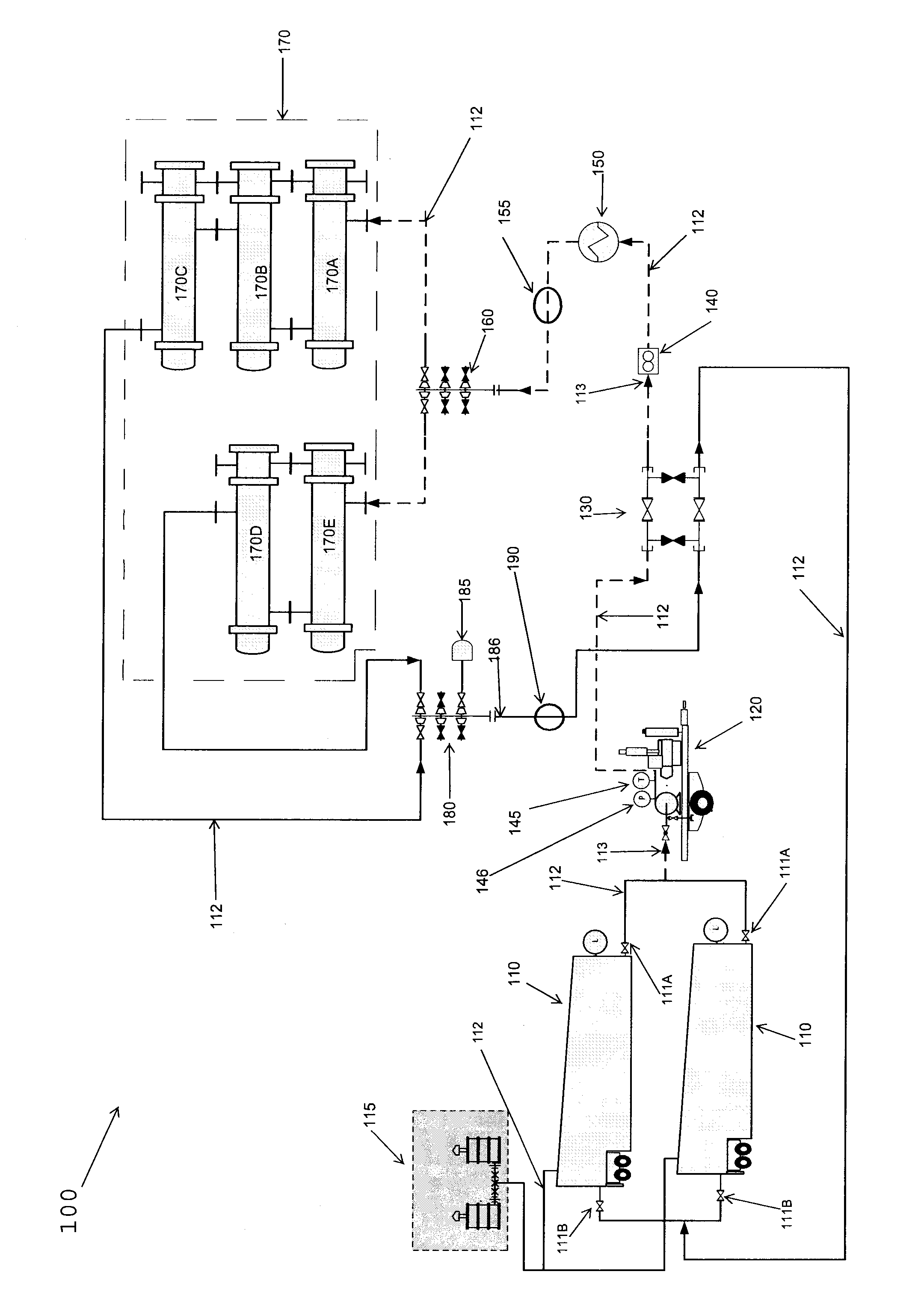
[0011]FIG. 1 is a diagram illustrating one embodiment of the present invention. In particular, FIG. 1 illustrates de-gassing, neutralizing, and decontamination system 100 or “DND” system 100. DND system 100, or de-gas / neutralize / decontaminate system 100 illustrates one embodiment of the present invention. As will be discussed in detail, DND system 100 is a system of circulating a specific chemical solution into process equipment 170 illustrated in FIG. 1. Process equipment 170 is process equipment in a manufacturing facility, such as a refinery or petrochemical manufacturing facility. In FIG. 1, process equipment 170 may be a series of exchangers identified as 170A-170E. While FIG. 1 illustrates process equipment 170 as a series of exchangers, the present invention is not limited to use on exchangers as it can be used on various equipment that is to be de-gassed, neutralized, and decontaminated. Through the present invention, the process equipment 170 (170A-170E) will be de-gassed, ...


PUM


Abstract

A system and method for de-gassing, neutralizing, and decontaminating various equipment with a clean hydrocarbon-free chemical solution such that maintenance of various equipment may begin sooner.

Description

TECHNICAL FIELD[0001]The present invention relates, in general to a de-gassing and neutralization process and system, and more specifically to the use of specific formulations and a specific system and process in order to de-gas and neutralize equipment including, but not limited to, refinery process equipment, in order to protect Austenitic stainless steels and other alloys from polythionic acid stress corrosion cracking in a shortened period of time.BACKGROUND OF INVENTION[0002]Currently, the energy industry is a rapidly expanding and very important industry for the day-to-day operations of society. Energy production comes from several sources, such as the petroleum industry, the gas industry, the electrical power industry, the coal industry, and the nuclear power industry. Some new energy industries include the renewable energy industry which includes alternative and sustainable manufacture, distribution, and sale of alternative fuels such as wind, solar, biodiesel, bioalcohol, c...

Claims


Application Information

Patent Timeline
IPC IPC(8): B08B9/032
CPCB08B9/0325B08B9/027
Inventor HAFFNER, KENNETHLUPER, RICHARD
Owner HAFFNER KENNETH
Why Eureka
Try Eureka