
Metering device, lubricating device and method for dispensing a predetermined amount of lubricant

a lubricating device and predetermined amount technology, applied in manual lubrication, machines/engines, distribution equipment, etc., can solve the problems of indirect bearing failure, high bearing and lubrication demands, and the effect of improving accuracy

Active Publication Date: 2015-09-29
AB SKF
View PDF16 Cites 6 Cited by
  • Summary
  • Abstract
  • Description
  • Claims
  • Application Information

AI Technical Summary

Benefits of technology

The patent describes a system that allows for precise lubrication of machine parts by using a microvalve to dispense lubricant. This system can be placed close to the machine part, reducing the supply path and improving precision. The lubricant reservoir can be located in a dangerous materials space, making it easier to adapt to installation conditions. The technical effects of this system are improved accuracy and efficiency in lubrication, better placement of the lubricant reservoir, and improved safety compliance.

Problems solved by technology

Studies have shown that a significant proportion of bearing failures is indirectly or directly attributable to an inadequate lubrication.
Besides an insufficient supplying with the lubricant, i.e. an insufficient lubrication per se, a fouling of the respective bearing can be, in particular, attributed indirectly to an inadequate lubrication.
Other reasons for bearing failures are frequently to be found, ranging from installation errors, an overloading, an occurrence of a mechanical bearing failure, or an operational error (handling error).
These demands, due on the one hand to the high rotational speeds and on the other hand to the limited installation space available, place very high demands on the bearing as well as on the lubrication.
But other technical fields wherein bearings are used also place increasing demands on the metering accuracy, the reaction time, the mobility and continuity, the monitoring, the environmental impact and the reliability of the lubricant supply.
A conventional grease lubrication is often no longer possible at high rotational speeds, and can even prove harmful in some applications.
Besides a significant consumption of compressed air, whose production leads to a significant energy consumption, moisture and / or contaminants can also be entrained with the auxiliary air stream, which deposit in the bearing and can lead to damage there.
Oil+air lubrication can thus often not facilitate a steady oil supply, and therefore can be inaccurate, as it is unclear how much oil is located exactly where in the interior of the nozzle and how much therefore exits through the nozzle in the form of a stream at a particular moment.
The oil+air lubrication can therefore have a certain latency period, and is therefore perceived as being sluggish.
A dispensing of the predetermined amount of lubricant can hereby be improved if necessary, since even small changes of the inner volume of the conduit system can be disadvantageous for the precision in light of the small volumes.

Method used


Image

  • Metering device, lubricating device and method for dispensing a predetermined amount of lubricant
  • Metering device, lubricating device and method for dispensing a predetermined amount of lubricant
  • Metering device, lubricating device and method for dispensing a predetermined amount of lubricant

Examples


Embodiment Construction

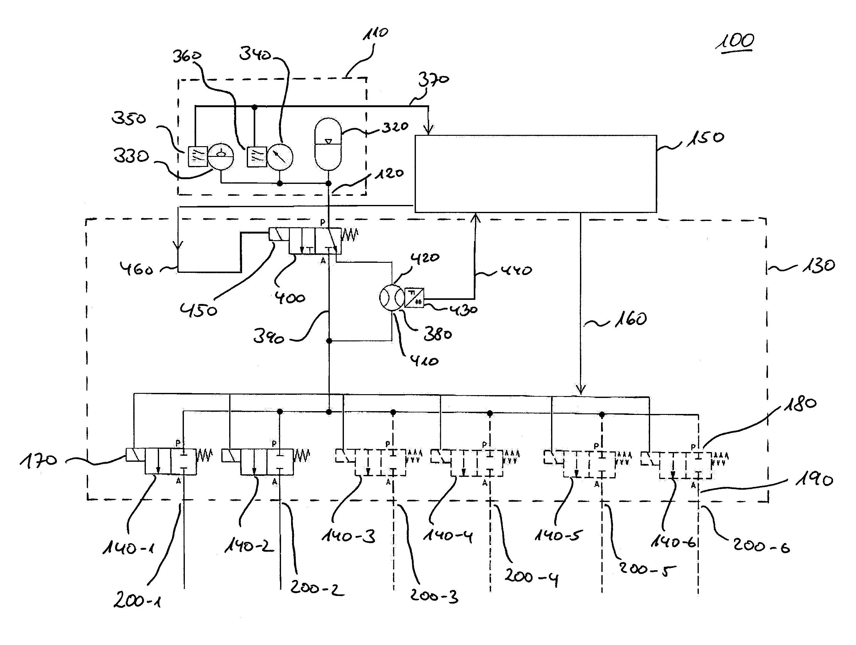
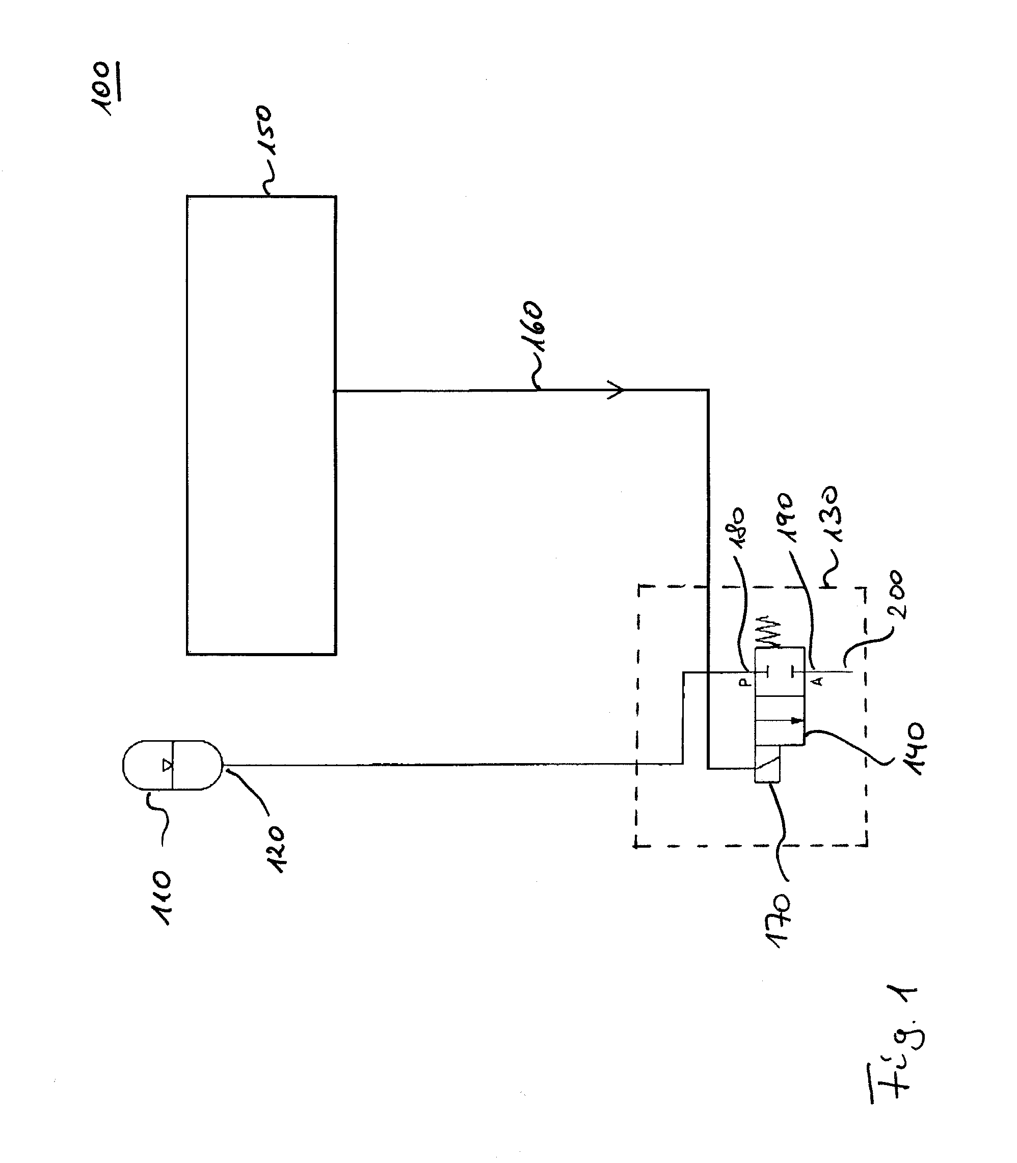
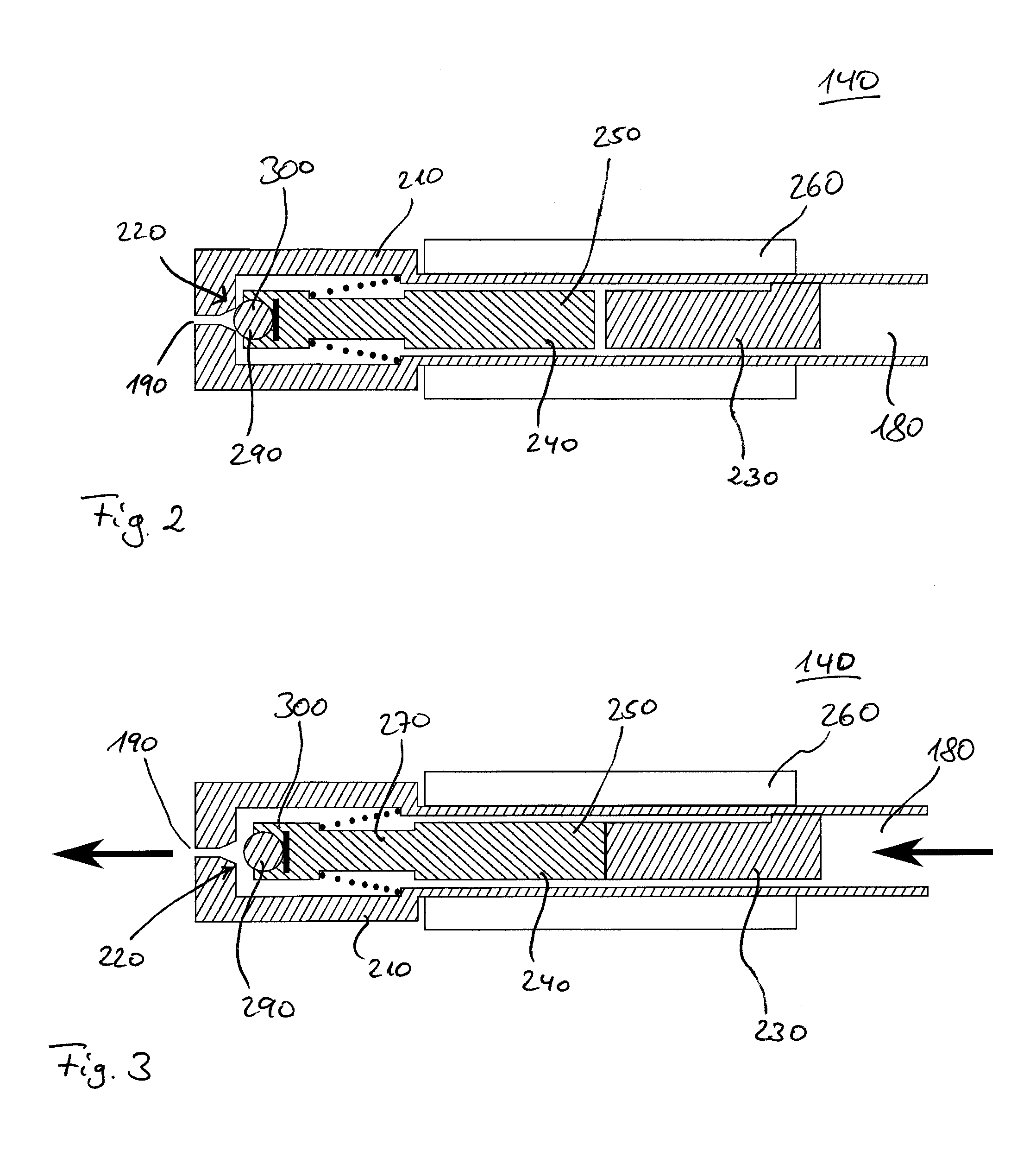
[0087]FIG. 1 shows a hydraulic plan of a metering device 100 according to an exemplary embodiment. The metering device for dispensing a predetermined amount of lubricant thus comprises a lubricant reservoir 110, which is formed to accommodate a lubricant and dispense it via an outlet 120 of the lubricant reservoir 110. Besides the lubricant reservoir 110, the metering device further has a metering apparatus 130, which is also referred to as metering unit. The metering apparatus 130 comprises a microvalve 140, which is fluidly coupled on the input side with the outlet 120 of the lubricant reservoir 110. The microvalve 140 is further formed to dispense the predetermined amount of lubricant. The metering device 100 further comprises an optional control circuit 150, which is also referred to as electronic unit. The control circuit 150 is in this case coupled with the microvalve 140 so that the control circuit 150 can output a control signal to the microvalve 140. For this purpose the co...


PUM


Abstract

A metering device for dispensing a predetermined amount of lubricant includes a lubricant reservoir, which retains a lubricant and dispenses it under pressure via an outlet of the lubricant reservoir, and a metering apparatus, which comprises at least one microvalve. The microvalve is fluidly coupled with the outlet of the lubricant reservoir and dispenses the predetermined amount of lubricant in a defined manner. The metering apparatus is spatially separable from the lubricant reservoir.

Description

TECHNICAL FIELD[0001]Exemplary embodiments relate to a metering device, a lubricating system and a method for dispensing a predetermined amount of lubricant.RELATED ART[0002]Many components of machines, and machine parts that move relative to one another, are guided or supported by bearings, in order for example to reduce wear or noise generation and thus increase the service life and / or maintenance intervals of the relevant machine or the relevant components. Bearings are used in a plurality of different embodiments, for example as sliding bearings or as rolling-element bearings. The type of relative motion, which is to be guided with the help of the bearing, determines at least partially the bearing technology that will be employed. Linear bearings are thus distinguished for example from other bearings that facilitate rotary movements (rotation) between components.[0003]Bearings are thus used in almost all mechanical components wherein relative movements occur. Here the requiremen...

Claims


Application Information

Patent Timeline
IPC IPC(8): F16N13/00F16N3/00F16N7/38F16N29/02
CPCF16N7/385F16N29/02F16N2270/30
Inventor KREUTZKAMPER, JURGENNELSON, HANS-DIETERSCHMIDT, FABIANSCHWARTZ, JORG
Owner AB SKF
Learn More