Unlock instant, AI-driven research and patent intelligence for your innovation.

Method for real-time, automatic, wideband, high accuracy RF direction finding

a technology of rf direction finding and real-time automatic detection, applied in the direction of multi-channel direction-finding systems using radio waves, instruments, measurement devices, etc., can solve the problems of serious performance and cost issues, adversely affecting processing efficiency, and high approach costs for the subset of real-world applications, so as to improve the probability of intercepting and throughput.

Active Publication Date: 2015-10-13
SECTRANETIX
View PDF3 Cites 0 Cited by
  • Summary
  • Abstract
  • Description
  • Claims
  • Application Information

AI Technical Summary

Benefits of technology

Enables efficient analysis of short duration signals across the entire RF band with improved throughput and accuracy, reducing costs and processing time while minimizing multipath errors, thereby enhancing the probability of intercept and accuracy of signal emitter location.

Problems solved by technology

However, these systems suffer from serious performance and cost issues in the face of short duration signals or situations that require analysis of the entire RF band.
This approach is very costly for the subset of real-world applications, often referred to as wideband applications, which require the analysis of large segments of the Electromagnetic Spectrum.
Generally, to keep costs down, fewer receiver channels are used which adversely effects processing efficiency as the system can only process small amounts of bandwidth simultaneously.
In addition, further serial processing is required if elevation and azimuth are desired compounding both cost and efficiency problems.
Multipath results in errors in the determination of the arrival angles.

Method used


Image

  • Method for real-time, automatic, wideband, high accuracy RF direction finding
  • Method for real-time, automatic, wideband, high accuracy RF direction finding
  • Method for real-time, automatic, wideband, high accuracy RF direction finding

Examples


Embodiment Construction

[0016]The following description is provided to enable any person skilled in the art to make and use the invention and sets forth the best modes contemplated by the inventor of carrying out his invention. Various modifications, however, will remain readily apparent to those skilled in the art, since the generic principles of the present invention have been defined herein specifically to provide a Method for Real-time, Automatic, Wideband, High Accuracy RF Direction Finding.

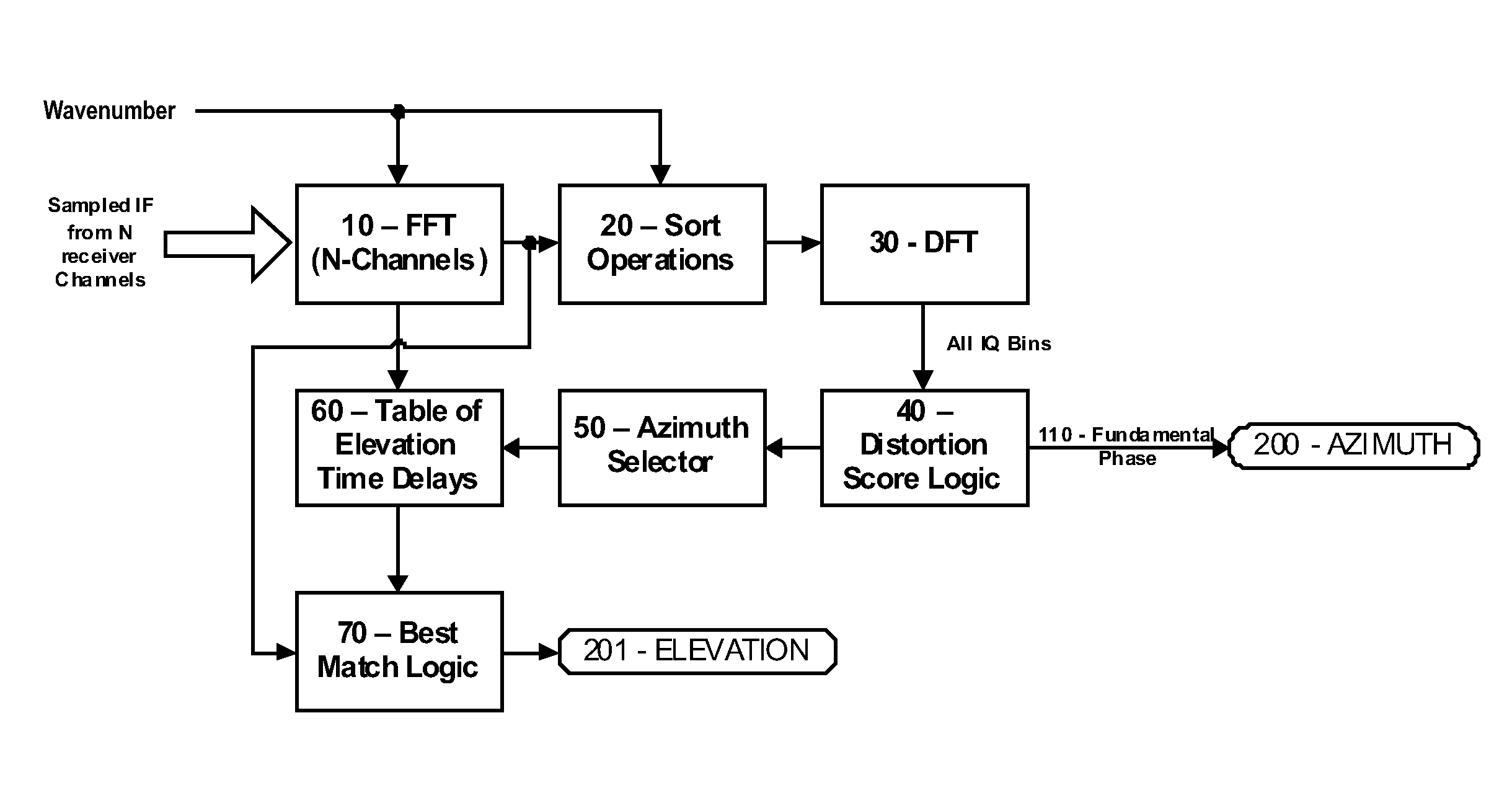
[0017]The present invention can best be understood by initial consideration of FIG. 1.1 FIG. 1 is a system diagram of an RF Direction Finding system. The array receives electromagnetic signals in the RF range that are then filtered for the desired frequency range and fed to high speed Analog-to-Digital Converters (A / D). There is one for each array element. It is also possible to reduce the number of receivers and A / D converters by utilizing multiplexing. As few as two receivers and two A / D converters could be used....


PUM


Abstract

This system and method provides a direction finding system that enables modern RF DF systems to analyze short duration signals in the entire instantaneous bandwidth. By providing a method to process wideband data, the invention drastically improves throughput and probability of intercept (POI). The invention is unique in that it does not require separate narrowband channels for analysis, and can simultaneously calculate azimuth and elevation estimates for every frequency in the bandwidth of an incident signal. It is also well-suited for fixed point, FPGA implementations making it a perfect match for modern state-of-the-art processing systems. The system and method capitalizes on the ability of Fourier Frequency Transform operations to accurately resolve incident wave phase at discrete frequencies. The system then uses the phase information from the individual elements in the array to arrive at an emitter azimuth angle. The azimuth angle is nearly simultaneously used in concert with lookup tables of all possible elevation angles to compare the arrival time delay between the array elements to determine emitter elevation angle.

Description

[0001]This application is filed within one year of, and claims priority to Provisional Application Ser. No. 61 / 548,112, filed Oct. 17, 2011.BACKGROUND OF THE INVENTION[0002]1. Field of the Invention[0003]This invention relates generally to signal transmitter locating systems and, more specifically, to a Method for Real-time, Automatic, Wideband, High Accuracy 3D RF Direction Finding.[0004]2. Description of Related Art[0005]This patent application describes an enhanced method for locating radio frequency signal emitters.[0006]Today's high frequency direction finding systems perform well in situations that require analysis on very few frequencies and when target signals are of constant frequency and long duration. However, these systems suffer from serious performance and cost issues in the face of short duration signals or situations that require analysis of the entire RF band. A modern RF DF system should process entire receiver bandwidths at speeds that enable it to analyze modern,...

Claims


Application Information

Patent Timeline
Patent Type & Authority Patents(United States)
IPC IPC(8): G01S5/02G01S3/74
CPCG01S3/74
Inventor KARLSSON, LARS
Owner SECTRANETIX