
Integrated tri-state electromagnetic interference filter and line conditioning module

a technology of electromagnetic interference filter and line conditioning module, which is applied in the direction of power conversion system, dc-dc conversion, instruments, etc., can solve the problems of reducing efficiency, compromising power converter design, and current related electromagnetic interference (emi) at their inputs, so as to increase the resistance of linear pass elements

Active Publication Date: 2015-10-13
CRANE ELECTRONICS INC
View PDF149 Cites 14 Cited by
  • Summary
  • Abstract
  • Description
  • Claims
  • Application Information

AI Technical Summary

Benefits of technology

This patent describes a method for controlling the output of a boost converter circuit using a boost output switch. The boost output switch can be enabled when the boost converter circuit is disabled and can be disabled when the boost converter circuit is enabled. The method also includes controlling the linear pass element of the EMI-LC circuit to increase its resistance when the voltage at the input of the EMI-LC circuit is above a certain level. This allows for better control of the output of the boost converter circuit. Overall, this method improves the efficiency and reliability of the boost converter circuit.

Problems solved by technology

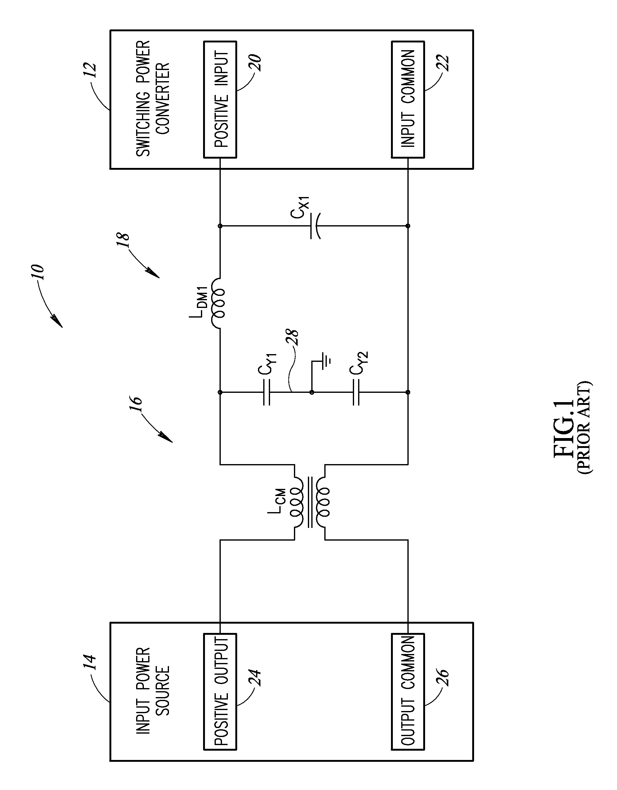
Switch-mode power converters (SMPCs) are a source of electromagnetic interference (EMI) in electronic equipment.
The main drawback of SMPCs is the current related electromagnetic interference (EMI) at their inputs and voltage related interference at their outputs.
Requiring a power converter to operate over the full input range when the input power source has a very wide input range (e.g., as much as 10:1) results in compromises to the power converter design, including lower efficiency.
Such designs also prevent use of existing available converters that are not designed for the required wide input range.
Moreover, use of separate functional blocks for EMI compliance, power conversion, and low-side (boost) or high side (clipping / limiting) functions can achieve good electrical performance but generally requires greater volume and higher cost.

Method used


Image

  • Integrated tri-state electromagnetic interference filter and line conditioning module
  • Integrated tri-state electromagnetic interference filter and line conditioning module
  • Integrated tri-state electromagnetic interference filter and line conditioning module

Examples


Embodiment Construction

[0031]In the following description, certain specific details are set forth in order to provide a thorough understanding of various disclosed embodiments. However, one skilled in the relevant art will recognize that embodiments may be practiced without one or more of these specific details, or with other methods, components, materials, etc. In other instances, well-known structures associated with the various embodiments have not been shown or described in detail to avoid unnecessarily obscuring descriptions of the embodiments.

[0032]Unless the context requires otherwise, throughout the specification and claims that follow, the word “comprising” is synonymous with “including,” and is inclusive or open-ended (i.e., does not exclude additional, unrecited elements or method acts).

[0033]Reference throughout this specification to “one embodiment” or “an embodiment” means that a particular feature, structure or characteristic described in connection with the embodiment is included in at lea...


PUM


Abstract

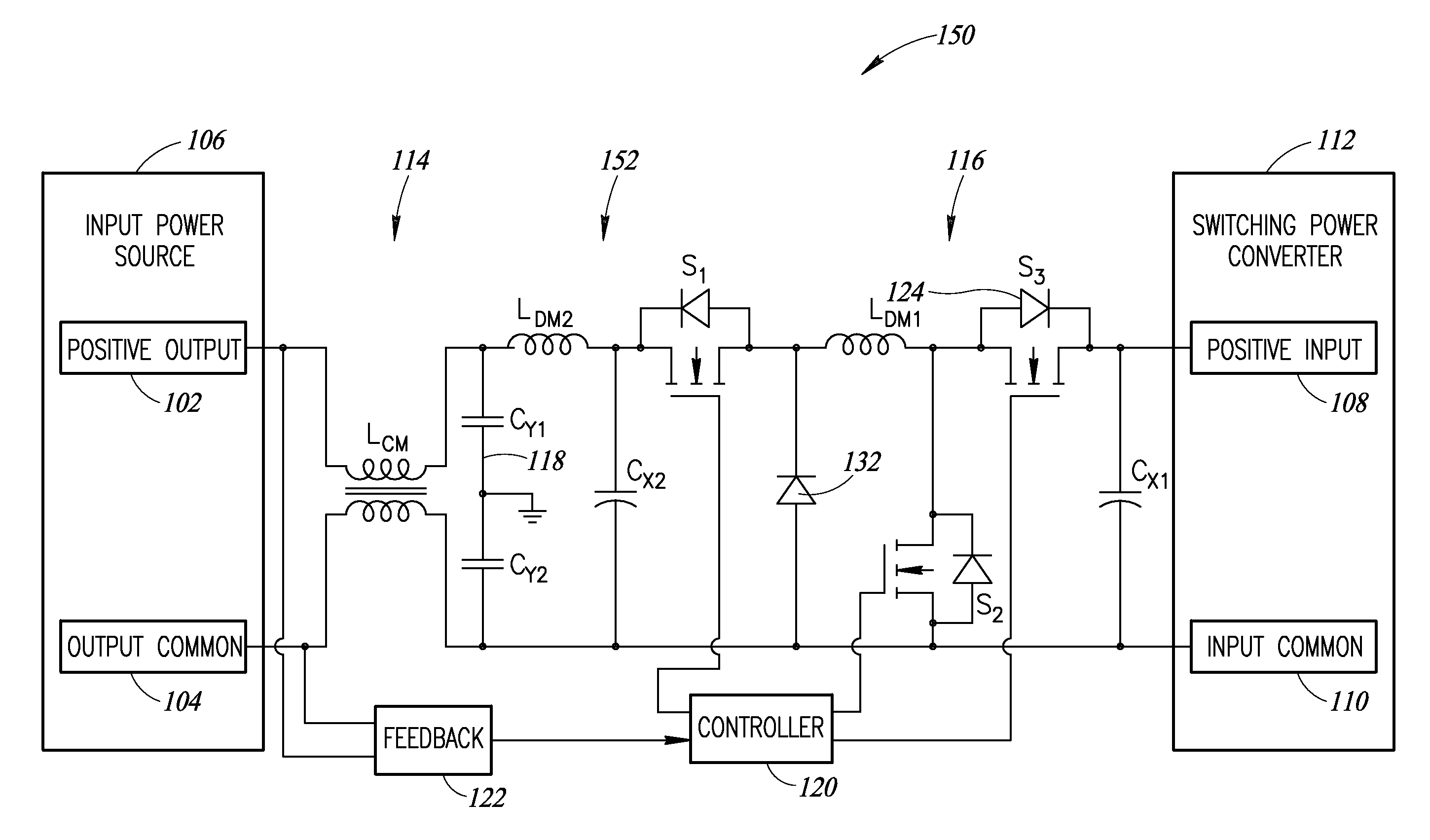
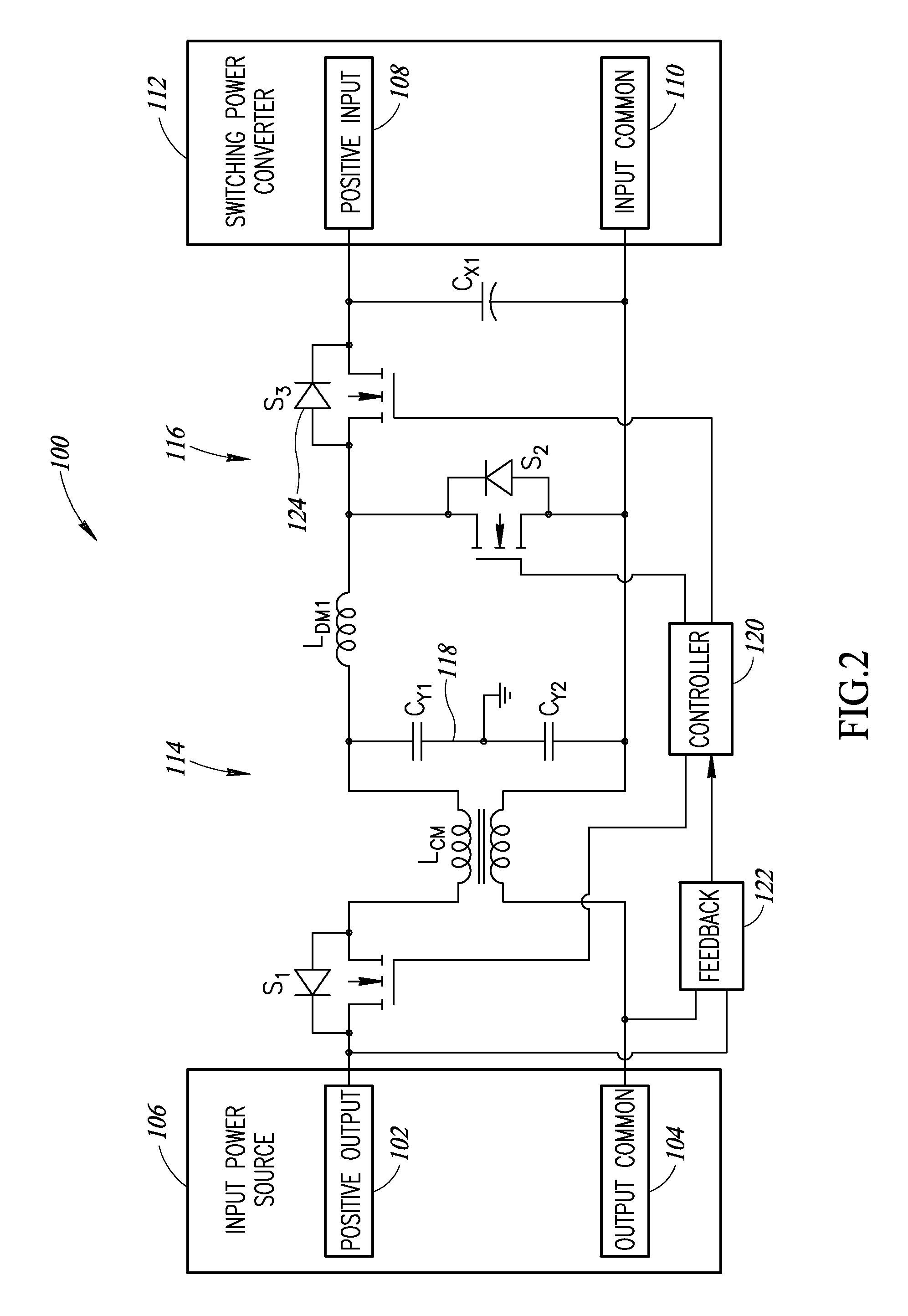
This disclosure describes systems, methods and articles of a passive EMI filter integrated with an active boost converter for low-side line transients and / or an active clipper for high-side line transients. During steady-state operation, the active circuitry is disabled so the circuit functions as a passive EMI filter. Inductive and capacitive components used in the passive EMI filter during steady-state operation may serve a dual role and become part of a boost converter when input voltage is below a low-line steady-state and, in some variations, the inductive and capacitive components may become part of a transient clipper when the input voltage is above a high-line steady-state level. The transient clipper may be implemented as a linear pass element or as a switch-mode converter (e.g., buck converter).

Description

BACKGROUND[0001]1. Technical Field[0002]The present disclosure generally relates to filtering and conditioning components for power systems.[0003]2. Description of the Related Art[0004]Direct current-to-direct current (DC / DC) converters that operate from vehicle power (e.g., spacecraft, aircraft, missiles, ground vehicles, marine applications) are designed to operate over a steady state voltage range around a nominal operating point, e.g., 28 V dc, and to accommodate transients at their input. The transients can be characterized as surges and sags in input voltage and voltage spikes of one sort or another. Generally, surges and sags are voltage increases / decreases that are of relatively long duration from sources with relatively low source impedance. Spikes are of much shorter duration, have higher amplitude, may be of either polarity, and are usually limited in energy.[0005]Switch-mode power converters (SMPCs) are a source of electromagnetic interference (EMI) in electronic equipme...

Claims


Application Information

Patent Timeline
Patent Type & Authority Patents(United States)
IPC IPC(8): H02M1/44H02M3/158
CPCH02M3/158H02M1/44H02M3/1582
Inventor PARKER, ERNESTLIU, DONGMINZLATEV, ANTON
Owner CRANE ELECTRONICS INC
Learn More