

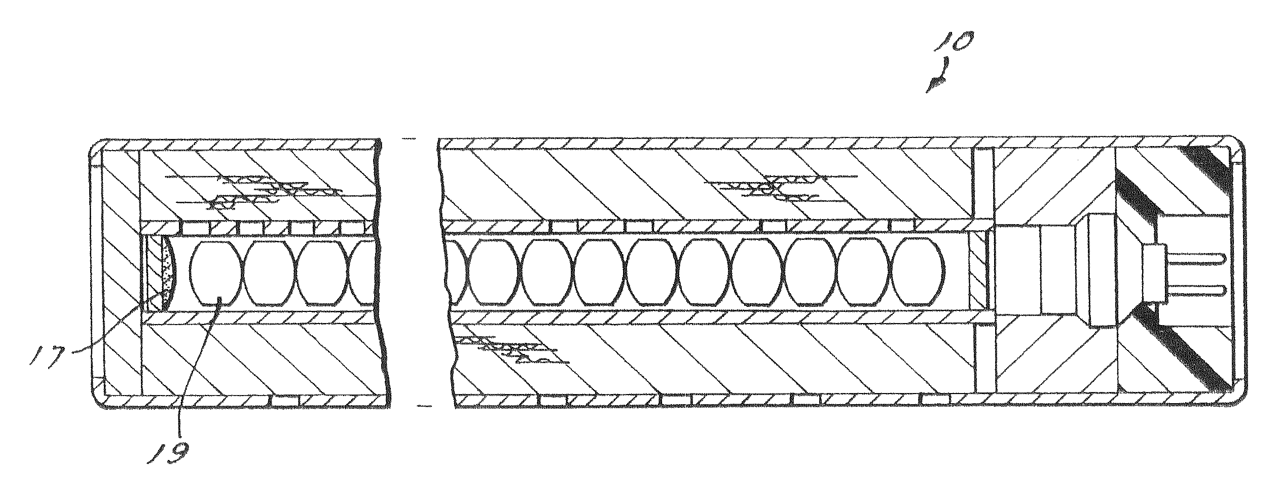
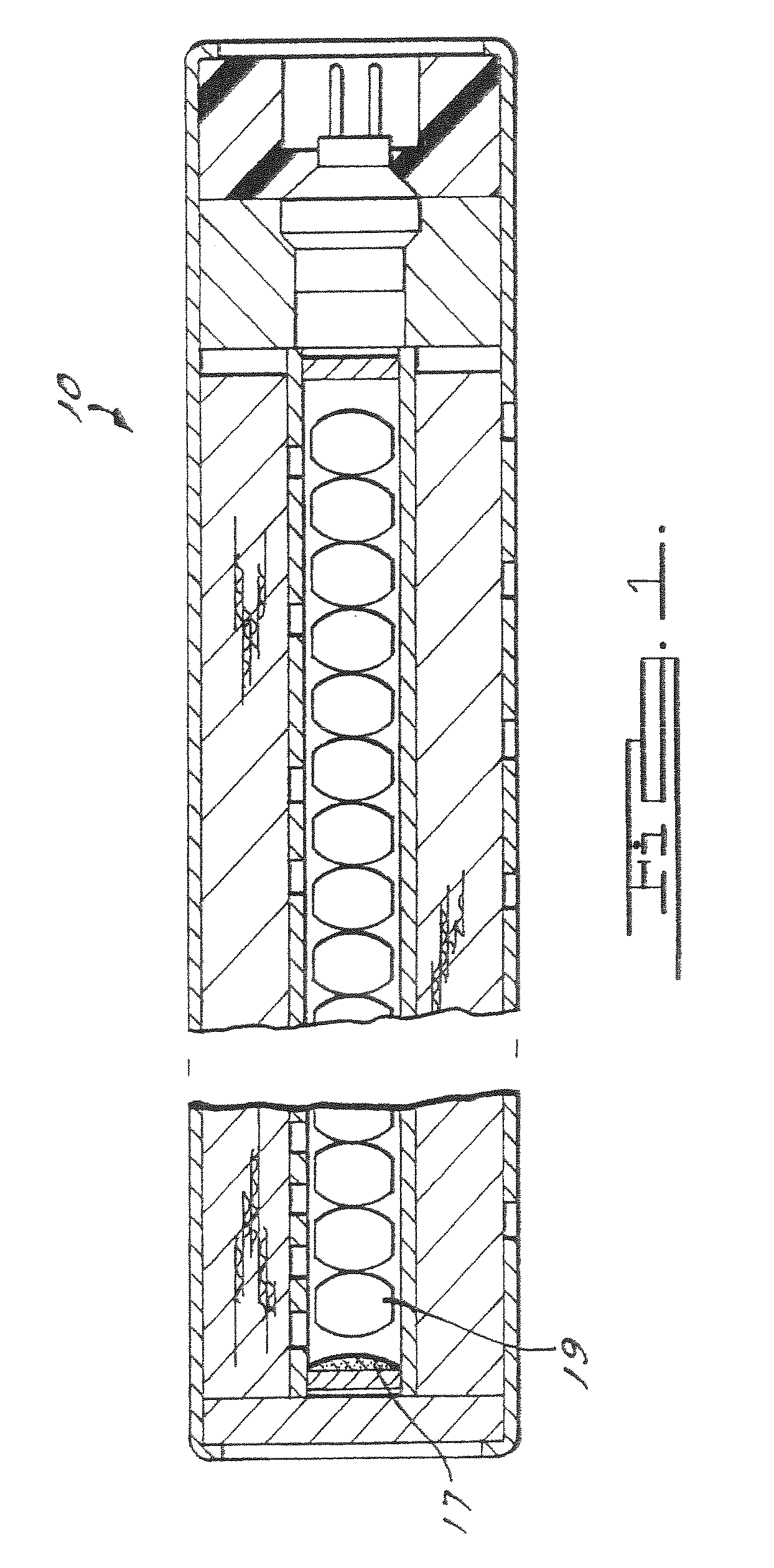
Auto-ignition composition
a technology of composition and ignition, applied in the field of auto-ignition composition, can solve the problems of mass detonation hazards of explosive devices, military ordnance or artillery shells, gas generators, etc., and achieve the effects of preventing mass detonation and safety concerns, facilitating safe deployment of associated devices, and reducing the risk of explosion
- Summary
- Abstract
- Description
- Claims
- Application Information
AI Technical Summary
Benefits of technology
Problems solved by technology
Method used
Image

Examples
example 1
[0033]An auto-ignition component is formed from about 35 wt % L-tartaric acid as a first fuel and 45 wt % of potassium chlorate as a first oxidizer, said percents taken by weight of the total composition. Silicone is provided at about 20 wt % of the total composition. The dry first fuel and dry first oxidizer, in granular form, are added to silicone and mixed to a homogeneous composition. The composition is then cured to provide an auto-ignition / booster composition.
[0034]A hot plate and DSC test were conducted. The hot plate test was done by heating the sample in a metal crucible at about 20 degrees C. per minute. The hot plate auto-ignition temperature was found to be 155 C. The Differential Scanning calorimetry (DSC) Test was conducted by increasing the heat applied to the sample at about 5 degrees C. per minute. The DSC auto-ignition onset temperature was found to be 143 C.
example 2
[0035]An auto-ignition component is formed from about 41 wt % DL-tartaric acid as a first fuel and 10 wt % of potassium chlorate as a first oxidizer, said percents taken by weight of the total composition. Next, 45 wt % of potassium perchlorate as a booster oxidizer, and 4 wt % of cellulose acetate butyrate (CAB) are provided, said percents taken by weight of the total composition. The first fuel, first oxidizer, and booster oxidizer are provided in dry granular form, and are then added to CAB and mixed to a homogeneous composition. The composition is then cured to provide an auto-ignition / booster composition.
[0036]A hot plate and DSC test were conducted. The hot plate test was done by heating the sample in a metal crucible at about 20 degrees C. per minute. The hot plate auto-ignition temperature was found to be 174 C. The Differential Scanning calorimetry (DSC) Test was conducted by increasing the heat applied to the sample at about 5 degrees C. per minute. The DSC auto-ignition o...
example 3
[0037]An auto-ignition component is formed from about 19.16 wt % DL-tartaric acid as a first fuel, 12.5 wt % succinic acid as a second fuel, and 16.67 wt % of potassium chlorate as a first oxidizer, said percents taken by weight of the total composition. Next, 35 wt % of potassium perchlorate as a booster oxidizer, and 16.67 wt % of chlorinated rubber as a binder are provided, said percents taken by weight of the total composition. The first and second fuels, first oxidizer, and booster oxidizer are provided in dry granular form, and are then added to uncured chlorinated rubber, and mixed to a homogeneous composition. The composition is then cured to provide an auto-ignition / booster composition.
[0038]A hot plate and DSC test were conducted. The hot plate test was done by heating the sample in a metal crucible at about 20 degrees C. per minute. The hot plate auto-ignition temperature was found to be 167 C. The Differential Scanning calorimetry (DSC) Test was conducted by increasing t...
PUM
| Property | Measurement | Unit |
|---|---|---|
| weight percent | aaaaa | aaaaa |
| weight percent | aaaaa | aaaaa |
| weight percent | aaaaa | aaaaa |
Abstract
Description
Claims
Application Information