
Rapid microfluidic thermal cycler for nucleic acid amplification

a microfluidic and thermal cycler technology, applied in the field of thermal cycling, can solve the problems of reducing the total time needed to complete the amplification, affecting the amplification efficiency of the sample, and generating differences in sample temperature,

Active Publication Date: 2015-10-27
RGT UNIV OF CALIFORNIA +1
View PDF13 Cites 2 Cited by
  • Summary
  • Abstract
  • Description
  • Claims
  • Application Information

AI Technical Summary

Benefits of technology

The present invention provides an apparatus and method for thermal cycling materials using a microfluidic heat exchanger. The apparatus includes a microfluidic heat exchanger, a porous medium, a microfluidic thermal cycling chamber, a working fluid at first temperature, a first system for transmitting the working fluid to the microfluidic heat exchanger, a second system for transmitting the working fluid to the microfluidic heat exchanger, a pump for flowing the working fluid, and a porous medium with uniform porosity or permeability. The invention has various applications, such as biowarfare detection, biomedical applications, and environmental monitoring. The invention is not limited to the specific forms disclosed and can be modified accordingly.

Problems solved by technology

Since the number of cycles is fairly large, this additional time unnecessarily heightens the total time needed to complete the amplification.In some previous automated PCR instruments, sample tubes are inserted into sample wells on a metal block.
However, in these previous instruments differences in sample temperature are generated by non-uniformity of temperature from place to place within the sample metal block.
Further, there are delays in transferring heat from the sample block to the sample, and those delays differ across the sample block.
These differences in temperature and delays in heat transfer cause the yield of the PCR process to differ from sample vial to sample vial.
The problems of minimizing non-uniformity in temperature at various points on the sample block, and time required for and delays in heat transfer to and from the sample become particularly acute when the size of the region containing samples becomes large as in the standard 8 by 12 microtiter plate.Another problem with current automated PCR instruments is accurately predicting the actual temperature of the reaction mixture during temperature cycling.
Actual measurement of the temperature of the mixture in each vial is impractical because of the small volume of each vial and the large number of vials.”
For example, for small lightweight refrigerators, compressors, evaporators and associated components of a vapor / liquid refrigerating cycle may be inconvenient and it has, therefore, been proposed to use the heat pump action of a Peltier pile.
Because the instrument has a large thermal mass and the sample vessels have low heat conductivity, cycling the required levels of temperature is inefficient.
The ramp time of the conventional thermal cycler is generally not rapid enough and inevitably results in undesired non-specific amplification of the target sequences.
The suboptimal performance of a conventional thermal cycler is also due to the lack of thermal uniformity widely acknowledged in the art.
Furthermore, the conventional real-time thermal cycler system carries optical detection components that are bulky and expensive.

Method used


Image

  • Rapid microfluidic thermal cycler for nucleic acid amplification
  • Rapid microfluidic thermal cycler for nucleic acid amplification
  • Rapid microfluidic thermal cycler for nucleic acid amplification

Examples


Embodiment Construction

[0040]Referring to the drawings, to the following detailed description, and to incorporated materials, detailed information about the invention is provided including the description of specific embodiments. The detailed description serves to explain the principles of the invention. The invention is susceptible to modifications and alternative forms. The invention is not limited to the particular forms disclosed. The invention covers all modifications, equivalents, and alternatives falling within the spirit and scope of the invention as defined by the claims.

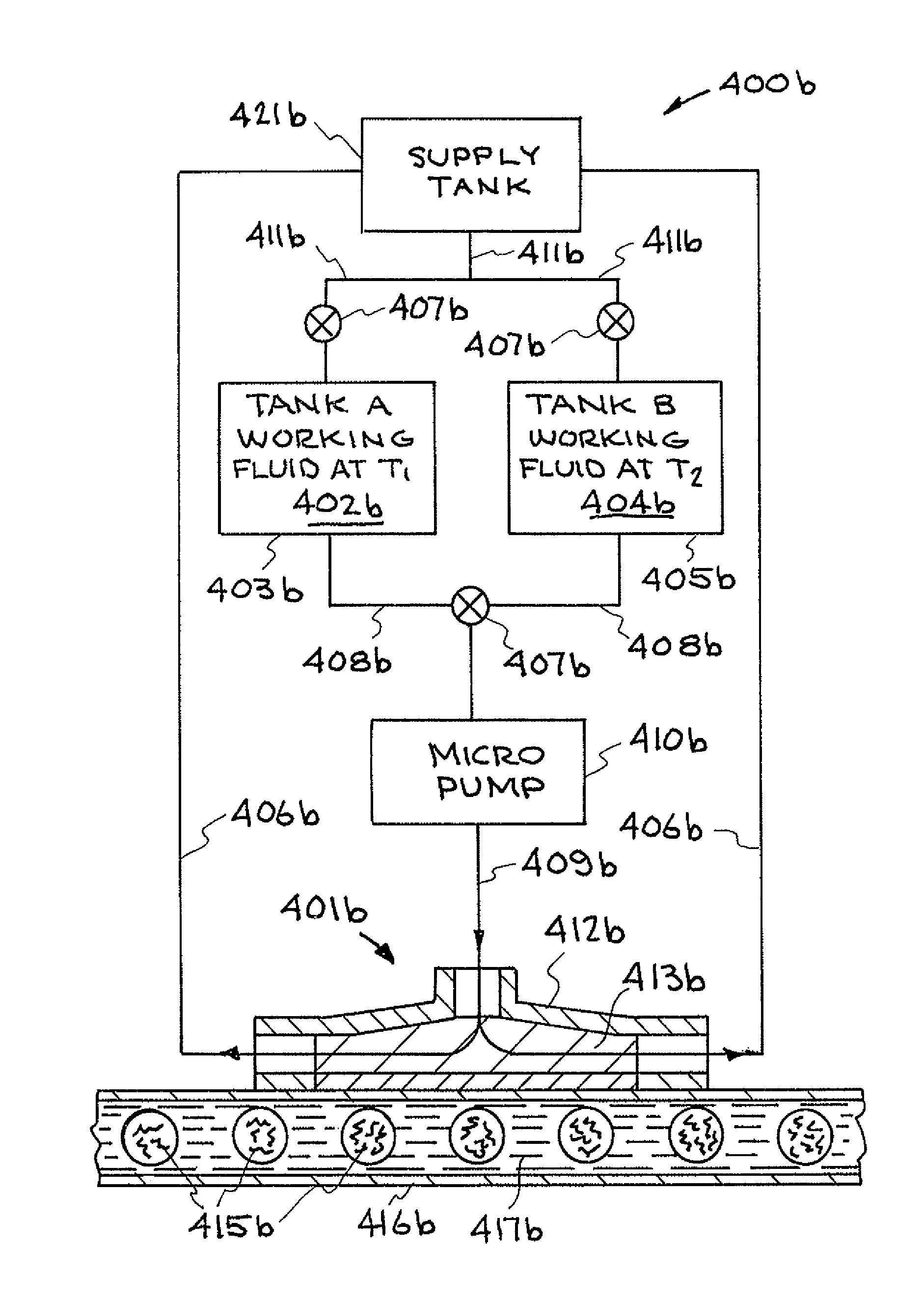
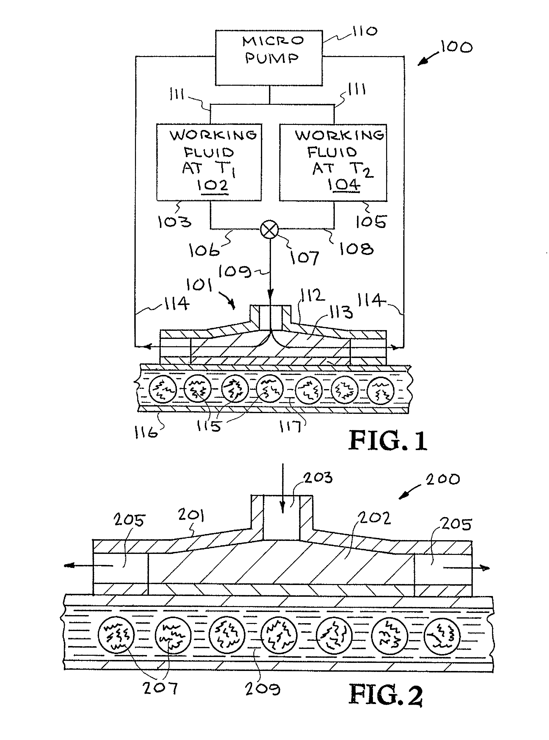
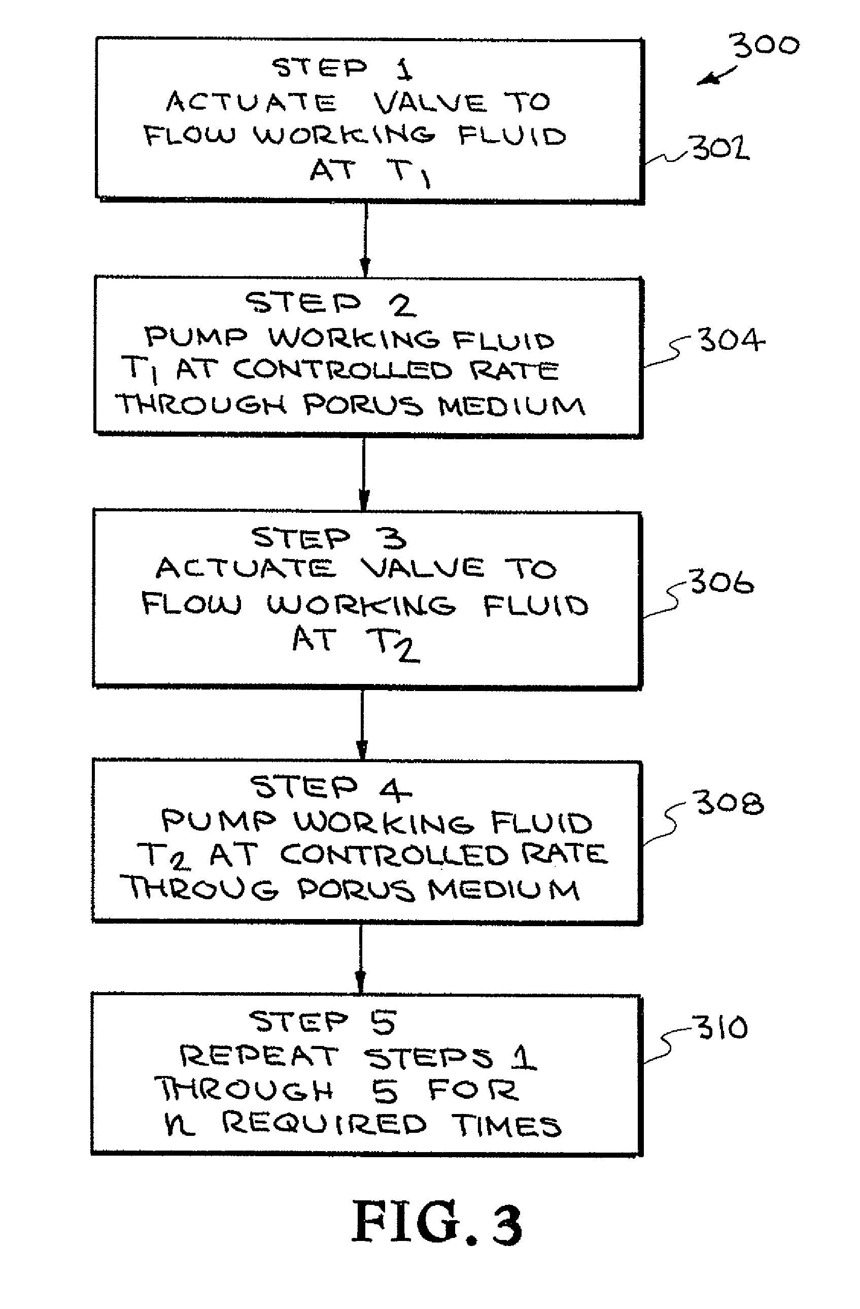
[0041]Referring now to the drawings and in particular to FIG. 1, one embodiment of a thermal cycling system constructed in accordance with the present invention is illustrated. The system is designated generally by the reference numeral 100. The system 100 will be described as a polymerase chain reaction (PCR) system; however, it is to be understood that the system 100 can be used as other thermal cycling systems.

[0042]PCR is the...


PUM

PropertyMeasurementUnit
temperaturesaaaaaaaaaa
temperatureaaaaaaaaaa

Abstract

A system for thermal cycling a material to be thermal cycled including a microfluidic heat exchanger; a porous medium in the microfluidic heat exchanger; a microfluidic thermal cycling chamber containing the material to be thermal cycled, the microfluidic thermal cycling chamber operatively connected to the microfluidic heat exchanger; a working fluid at first temperature; a first system for transmitting the working fluid at first temperature to the microfluidic heat exchanger; a working fluid at a second temperature, a second system for transmitting the working fluid at second temperature to the microfluidic heat exchanger; a pump for flowing the working fluid at the first temperature from the first system to the microfluidic heat exchanger and through the porous medium; and flowing the working fluid at the second temperature from the second system to the heat exchanger and through the porous medium.

Description

CROSS-REFERENCE TO RELATED APPLICATIONS[0001]The present application claims benefit under 35 U.S.C. §119(e) of U.S. Provisional Patent Application No. 61 / 022,647 filed on Jan. 22, 2008 entitled “rapid microfluidic thermal cycler for nucleic acid amplification,” the disclosure of which is hereby incorporated by reference in its entirety for all purposes. Related inventions are disclosed and claimed in U.S. patent application Ser. No. 12 / 270,030 titled Portable Rapid Microfluidic Thermal Cycler for Extremely Fast Nucleic Acid Amplification filed on Nov. 13, 2008. The disclosure of U.S. patent application Ser. No. 12 / 270,030 titled Portable Rapid Microfluidic Thermal Cycler for Extremely Fast Nucleic Acid Amplification is hereby incorporated by reference.STATEMENT AS TO RIGHTS TO INVENTIONS MADE UNDER FEDERALLY SPONSORED RESEARCH AND DEVELOPMENT[0002]The United States Government has rights in this invention pursuant to Contract No. DE-AC52-07NA27344 between the United States Department...

Claims


Application Information

Patent Timeline
Patent Type & Authority Patents(United States)
IPC IPC(8): C12M1/00C12M3/00F28F13/00B01L7/00F28F3/12B01L3/00
CPCF28F13/003B01L3/502784B01L7/52F28F3/12B01L3/5023B01L2300/0636B01L2300/0816B01L2300/0838B01L2300/185B01L2300/1838F28F2260/02
Inventor BEER, NEIL REGINALDVAFAI, KAMBIZ
Owner RGT UNIV OF CALIFORNIA
Learn More