Photobioreactor and method for processing polluted air

Active Publication Date: 2015-11-03
PHYCO2 LLC
View PDF1 Cites 0 Cited by
  • Summary
  • Abstract
  • Description
  • Claims
  • Application Information

AI Technical Summary

Benefits of technology

This patent describes a system for processing polluted air by sequestering harmful emissions. The system includes two tubes, a head cap assembly, and a base assembly that form a fluidly interconnected circuit. A light source is positioned inside the helical portion of one of the tubes, and a photosynthetic organism is present in a fluid medium in the circuit. Additionally, a sparger may be added to create gas bubbles with carbon dioxide into the fluid medium. The technical effects of this system include its ability to effectively remove harmful emissions from polluted air and create a safe and clean atmosphere.

Problems solved by technology

In addition to the carbon dioxide emitted from electric power plants, which are some of the biggest producers of such gases, other sources of harmful emissions include manufacturing facilities and diesel power generation plants, to note but a few.
The open channel photobioreactors, such as ponds, have faced difficulties from contamination by hostile species or external pollutants and from the inefficient use of light that illuminates only the top portion of the pond.
This, however, greatly increases land space requirements for pond-based photobioreactors.
In addition, when these ponds use natural sunlight the process is limited by the available hours of sunlight.
Such processing limitations can be important if the photobioreactors are used to process waste gasses from polluting facilities that operate twenty-four hours a day.
Further, if these ponds are not insulated from the elements such as seasonal changes in weather, the photosynthetic organisms must be remarkably hardy to withstand changes in temperature, external pollution, and attack from hostile species.
Conventional air lift photobioreactors, however, suffer from the lack of flow patterns that can be duplicated, controlled, or even easily defined.
Difficulty controlling the mixing properties may lead to poor photomodulation, low mass transfer coefficients, and low productivity.
In addition, systems having uncontrolled or poorly controlled fluid flow or mixing properties may experience algae pooling or buildup along with damage to the photosynthetic organism that results in poor algal growth.

Method used


Image

  • Photobioreactor and method for processing polluted air
  • Photobioreactor and method for processing polluted air
  • Photobioreactor and method for processing polluted air

Examples


Embodiment Construction

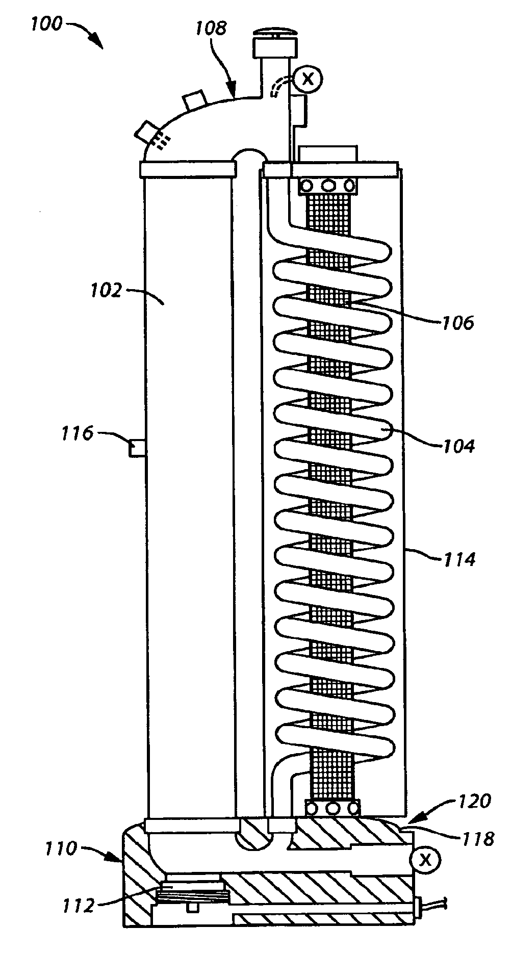
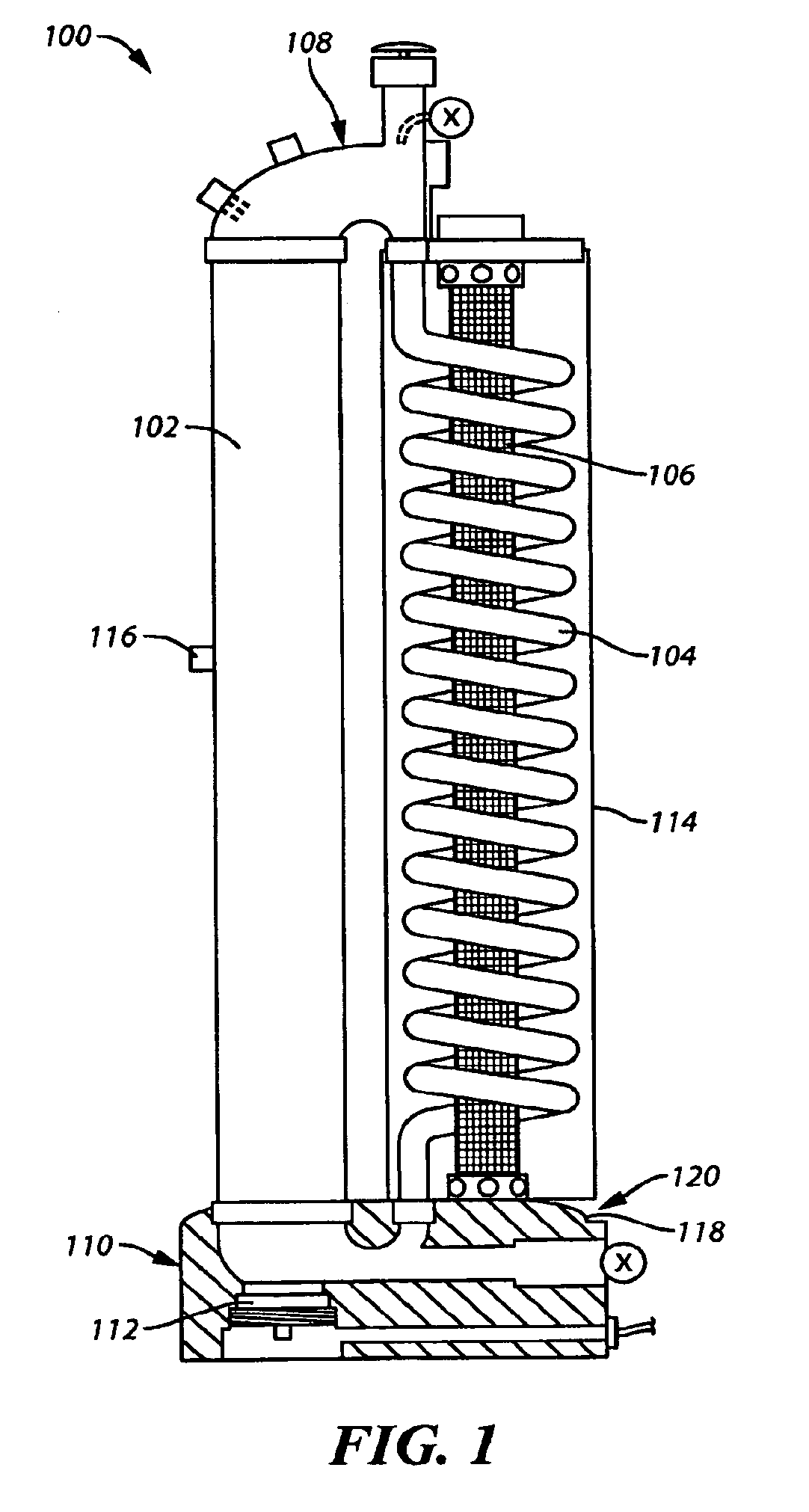
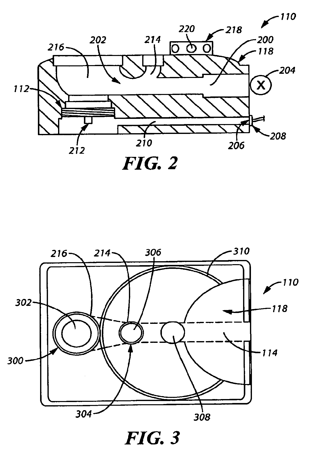
[0037]Generally speaking, pursuant to these various embodiments, a photobioreactor is disclosed herein having a generally vertical fluidic pathway and a generally vertical helically shaped fluidic pathway. As used herein, the generally vertical helically shaped pathway is vertical in that the fluid medium moving within the pathway is displaced over a substantially vertical distance. The two fluidic pathways are fluidly connected by a head cap assembly and a base assembly such that a biologically active material is able to move fluidly, without substantial impediment, back and forth between the generally vertical fluidic pathway and the generally vertical helically shaped fluidic pathway.

[0038]By one approach, a light source is at least partially positioned inside a portion of the generally vertical helically shaped fluidic pathway. The light source may be a light emitting diode (LED). By one approach, this light source can comprise a plurality of light emitting diodes (LEDs). Furthe...


PUM


Abstract

A photobioreactor (100) for use in treating polluted air and producing biomass may comprise, at least in part, a generally vertical tube or fluidic pathway (102), a generally vertical helical tube or fluidic pathway (104) having a light source (106) partially positioned within the helical fluidic pathway (104), a head cap assembly (108), and a base assembly (110). In one illustrative example, the light source (106) may be a light emitting diode (LED) or a plurality of light emitting diodes (LEDs). By one approach, a gas diffusion apparatus (112) is located at the base assembly (110) adjacent the generally vertical fluidic pathway (102).

Description

CROSS-REFERENCE TO RELATED APPLICATIONS[0001]This application is a divisional application of U.S. application Ser. No. 12 / 526,151, filed Aug. 6, 2009, which claims the benefit of International Application No. PCT / US2008 / 052801, filed Feb. 1, 2008, designating the United States and claiming priority to U.S. Patent Application No. 60 / 899,662, filed Feb. 6, 2007, all of which are incorporated by reference herein in their entirety.TECHNICAL FIELD[0002]This invention relates generally to photobioreactors, and more particularly to algal photobioreactors suitable for use in sequestering harmful emissions and producing biomass.BACKGROUND[0003]Bioreactors, including photobioreactors using the principles of photosynthesis, are well known in the art. Photobioreactors use photosynthetic organisms such as algae in a liquid medium along with light energy (whether synthetic light or natural sunlight) and carbon dioxide to create chemical energy from light energy while sequestering carbon dioxide. ...

Claims


Application Information

Patent Timeline
IPC IPC(8): C12M1/42C12M1/12C12M1/00
CPCC12M21/02C12M23/06C12M29/18C12M31/02B01D53/84C12N1/12
Inventor MORGAN, ROBERT
Owner PHYCO2 LLC
Why Eureka
Try Eureka