Drilling control method and system

a control method and control system technology, applied in the direction of instruments, electrical digital data processing, structural/machine measurement, etc., can solve the problems of increasing the difficulty of drilling oil and gas wells, the difficulty of both formation stability and narrowing pressure windows, and the running of a remedying script, so as to minimize the effect of the critical situation

Active Publication Date: 2015-11-03
SEKAL AS
View PDF56 Cites 35 Cited by
  • Summary
  • Abstract
  • Description
  • Claims
  • Application Information

AI Technical Summary

Benefits of technology

[0026]The method may also involve applying automated data quality control through filtering applications, such as FIR / MR filtering and automatic high pass coefficient distribution analysis, allowing for smoothing and detection of outliers (or invalid measurements).

Problems solved by technology

The challenges in controlling the drilling process are not new, but drilling of oil and gas wells is becoming more and more of a challenge.
Known reservoirs are being depleted, leading to problems with both formation stability and narrowing pressure windows.
In addition, it contains automated analysis of the drilling conditions, which can result in running of a remedying script if an undesired condition is detected.
Full optimization with respect to individual mechanisms may be detrimental to other process mechanisms.
As an example, fully optimized rate of penetration with respect to specific mechanical energy, through adjustment of WOB and RPM may lead to cuttings build-up issues if the pump rate is not adjusted accordingly, which is further constrained by the existing formation geopressures.
Since all decision making is done by the operator based on availability of information, there will always be a time delay before any action is taken when undesired symptoms are observed.
During this delay there is a great risk of the observed problem escalating and becoming more severe (e.g. pressure buildup).
This is one of the major challenges of today's drilling process.
The full know-how of the organization is not applied, and inappropriate mediating actions may cause loss of time, loss of production, and possibly loss of the well.

Method used


Image

  • Drilling control method and system
  • Drilling control method and system
  • Drilling control method and system

Examples


Embodiment Construction

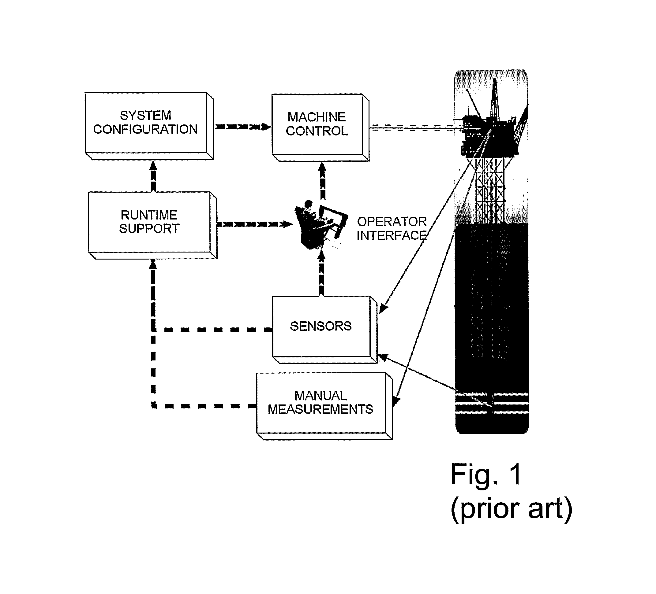
[0054]FIG. 1 illustrates a known set-up for a drilling process. For drilling of oil and gas wells, such a drilling control system (DCS) can be used on the drilling rig. A DCS of the prior art may consist of sensors for measuring drilling parameters, computer controlled drilling machinery with computer aided machine control, and a human operator interface. The objective of such a system is to aid the driller (or operator) in controlling drilling process parameters, such as velocity of the drill string when running in and out of the borehole, or wellbore fluid flowrate, through application of software control algorithms embedded in the machine control.

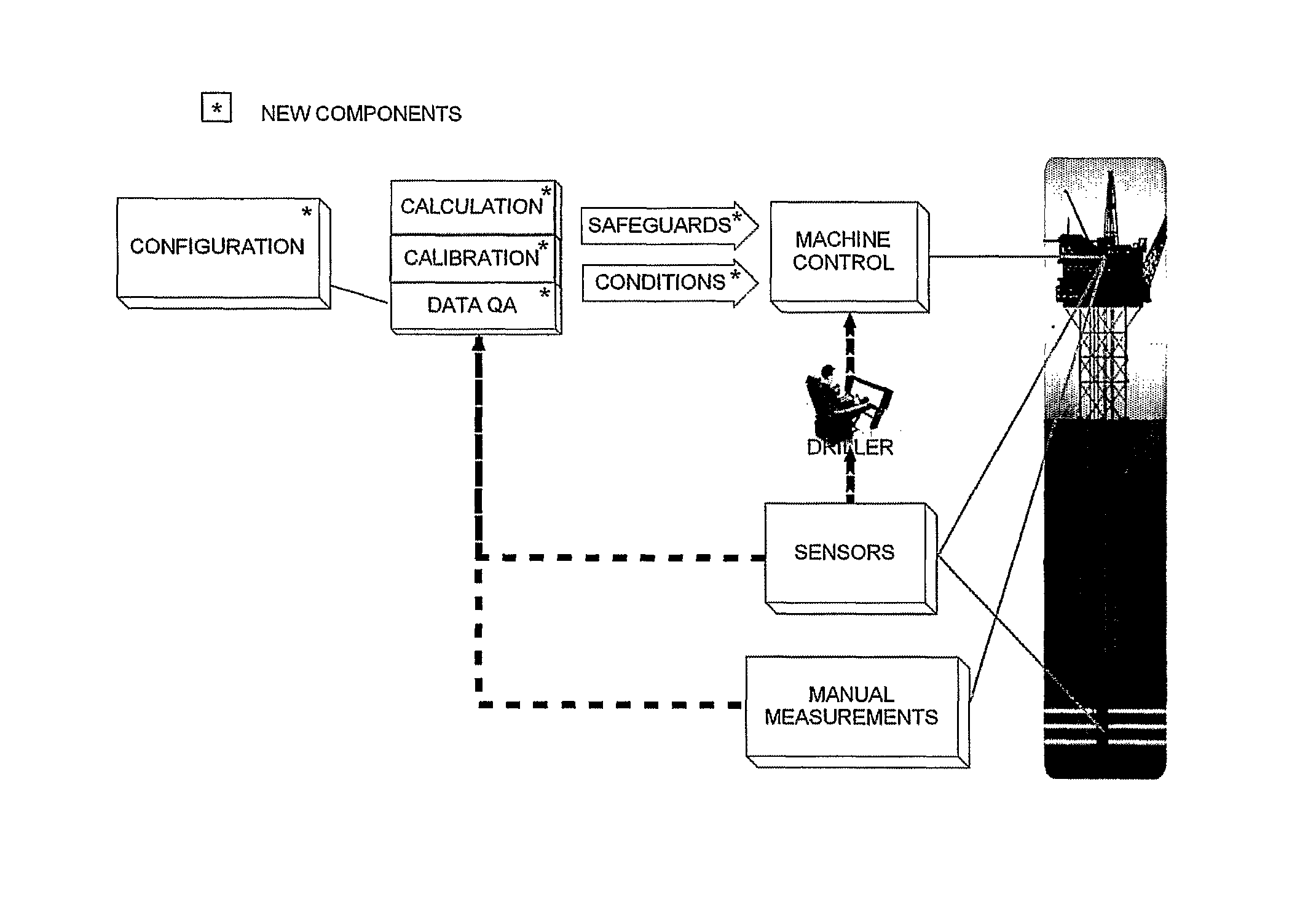
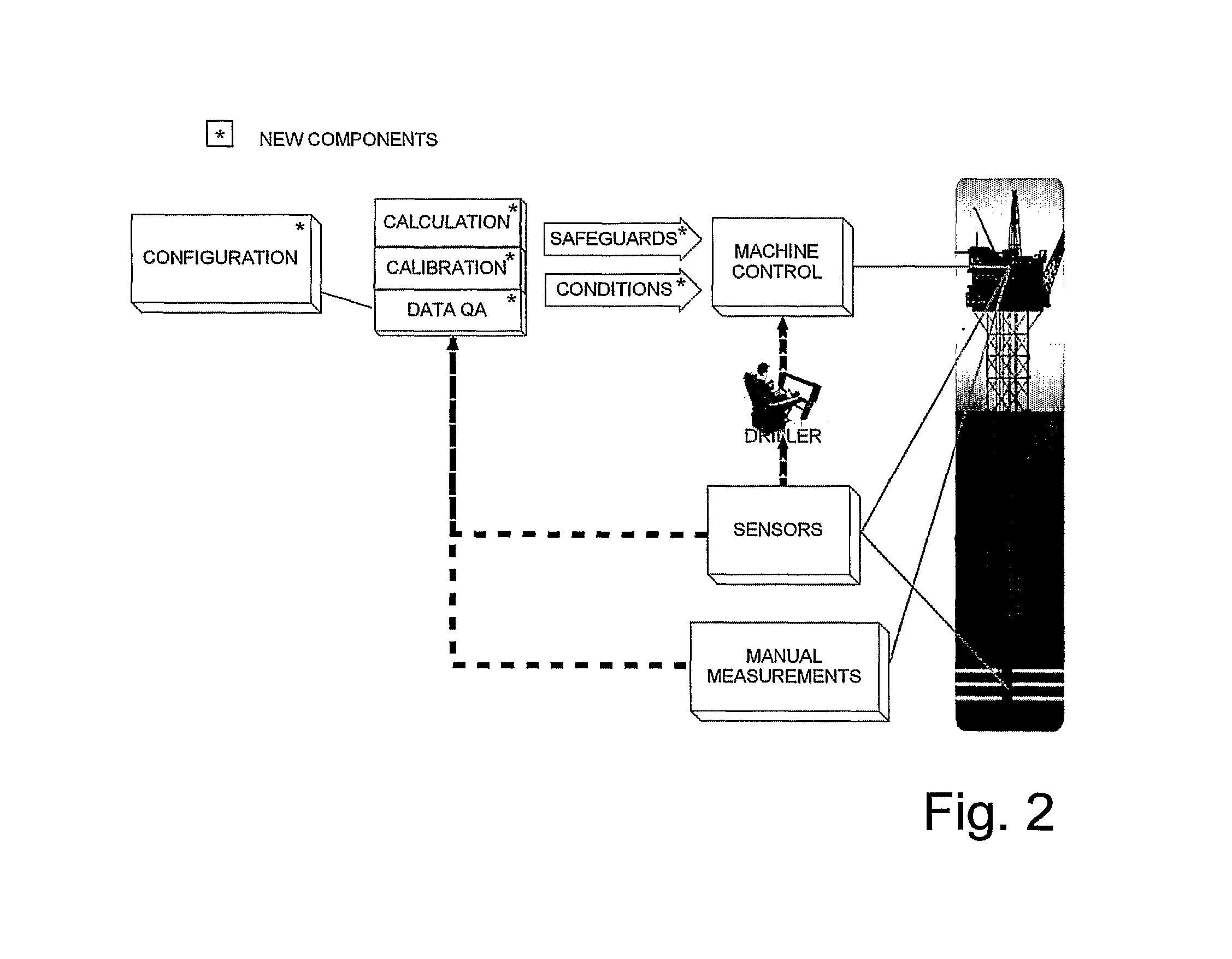
[0055]In addition to the manual control of parameters performed by the operator or driller in FIG. 1, there may be manually tunable parameters in the MACHINE CONTROL, such as constant WOB or ROP settings which may be automatically enforced by the system through application of process control during drilling operations, though application...


PUM


Abstract

Method and system for drilling control comprising a plurality of controllers adapted to control performance process parameters, on the basis of driller controls from a driller that provides this as instructions to said controllers, wherein the system further comprises sensors and means for obtaining process values, such as downhole pressure, temperature and torque, wherein the system is adapted to, continuously and / or repeatedly, calculate safeguard envelopes for performance process parameters on the basis of process values and drilling process models and that it is adapted to restrain said controllers from applying performance process parameters outside said safeguard envelopes as a result of driller instructions, and—a method and system for automatically triggering a remedying action in case of an evolving or existing critical situation, comprising calculation of process parameter boundaries which represent a critical condition for the well by using calibrated drilling process models, comprising (i) triggering an emergency action if a parameter exceeds said boundaries, said emergency action being intended to minimize the effect of said critical situation, (ii) then further analyzing the well in order to determine which remedying action to then be applied, the remedying action being intended to remedy the cause of said effect; (iii) if said remedying action is not capable of remedying the cause of said effect, then applying predetermined safe process parameters or shutting down.

Description

[0001]This application is entitled to the benefit of, and incorporates by reference essential subject matter disclosed in PCT Application No. PCT / NO2010 / 000081 filed on Mar. 1, 2010, which claims priority to Norway Application No. 20090935 filed Mar. 2, 2009.BACKGROUND OF THE INVENTION[0002]1. Technical Field[0003]The present invention relates to drilling of hydrocarbon wells. In particular, the invention relates to a method and a drilling control system for providing risk reduction and improved efficiency of a drilling process.[0004]2. Background Information[0005]When drilling a hydrocarbon well, such as a subsea well, it is known to operate the drilling equipment through a computerized drilling system. The drilling operator controls the various parameters of the process using control devices such as joysticks, throttles or switches. The control devices are connected to equipment controls, such as a controller for the rotary table.[0006]When drilling such a well, one wishes to dril...

Claims


Application Information

Patent Timeline
Patent Type & Authority Patents(United States)
IPC IPC(8): G06F19/00E21B44/00
CPCE21B44/00
Inventor IVERSEN, FIONNCAYEUX, ERIC
Owner SEKAL AS
Why Eureka
Try Eureka