Component of an EUV or UV lithography apparatus and method for producing it

a technology of lithography apparatus and euv, which is applied in the direction of printers, instruments, paper/cardboard containers, etc., can solve the problems of additional stress in the bonded parts, and achieve the effect of reducing the influence and high precision

Active Publication Date: 2015-11-03
CARL ZEISS SMT GMBH
View PDF20 Cites 2 Cited by
  • Summary
  • Abstract
  • Description
  • Claims
  • Application Information

AI Technical Summary

Benefits of technology

[0005]It is an object of the invention to improve the bonding of two parts of a component of an EUV or UV lithography apparatus such that the probability of occurrence of additional stress over time in the bonded parts is lessened.
[0007]By insulating at least partly the surface of the adhesive material between the bonded parts that is exposed to the surrounding gas environment, the influence of the gas environment can be decreased. Gases in the surrounding environment, that are apt to be absorbed by the adhesive material, thus causing expansion or degradation of the adhesive material, have a much lesser probability of reaching the adhesive material. Gases in the adhesive material that could outgas, thus causing shrinking of the adhesive material, have a much lesser probability of outgassing, due to the protective layer. The shrinking or expansion or degradation of the adhesive material could otherwise lead to additional stress in the bonded parts, depending on the particular composition of the surrounding gas environment. It will be noted that in addition to the adhesive bonding further bonding methods and structures may be utilized.
[0009]In particular in the projection system, the tolerance ranges for the optical characteristics are quite tight to accurately project the structure of an illuminated mask on a wafer. By avoiding additional stress due to expansion or shrinking or degradation of the adhesive material used for bonding parts of components of the projection system, these tolerance ranges may be easier to control.
[0010]In a third aspect of the present invention, the object is achieved by an EUV or UV lithography apparatus including a component as explained, thus allowing for a higher precision of the lithography process.
[0014]By depositing a protective layer on the adhesive material after bonding, at least part of the surface of adhesive material that would otherwise be exposed to the surrounding gas environment after bonding is insulated by the protective layer, thus reducing the influence of the surrounding gas environment on the adhesive material, which could otherwise lead to additional and time-varying stress in the bonded parts. Components for EUV or UV lithography apparatuses produced according to this method allow for lithography apparatuses and projection systems for EUV or UV lithography with high precision.

Problems solved by technology

The shrinking or expansion or degradation of the adhesive material could otherwise lead to additional stress in the bonded parts, depending on the particular composition of the surrounding gas environment.

Method used


Image

  • Component of an EUV or UV lithography apparatus and method for producing it
  • Component of an EUV or UV lithography apparatus and method for producing it
  • Component of an EUV or UV lithography apparatus and method for producing it

Examples


Embodiment Construction

is provided below. The description is provided by way of non-limiting examples, to be read with reference to the attached drawings in which:

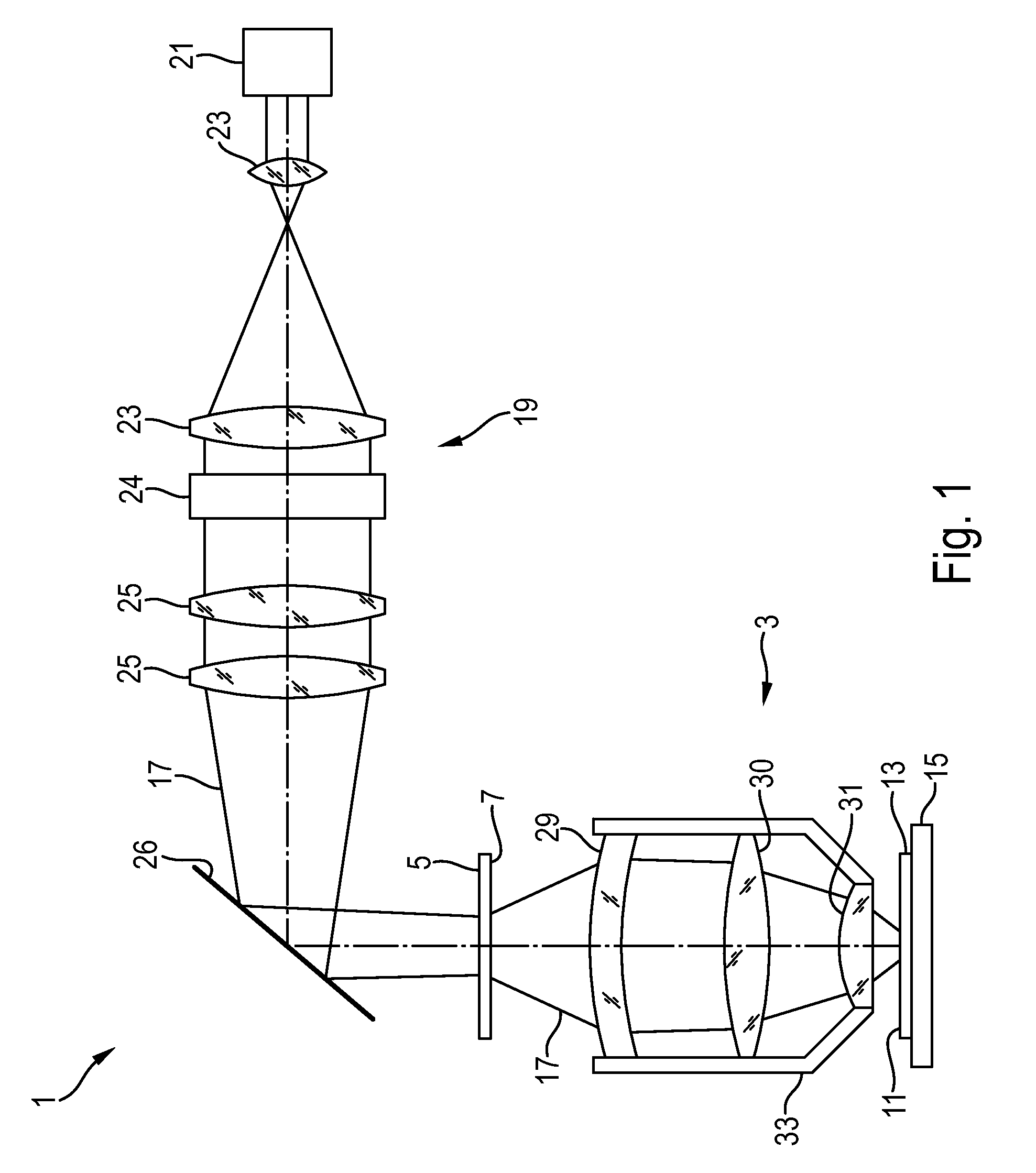
[0017]FIG. 1 illustrates schematically an embodiment of a UV lithography apparatus;

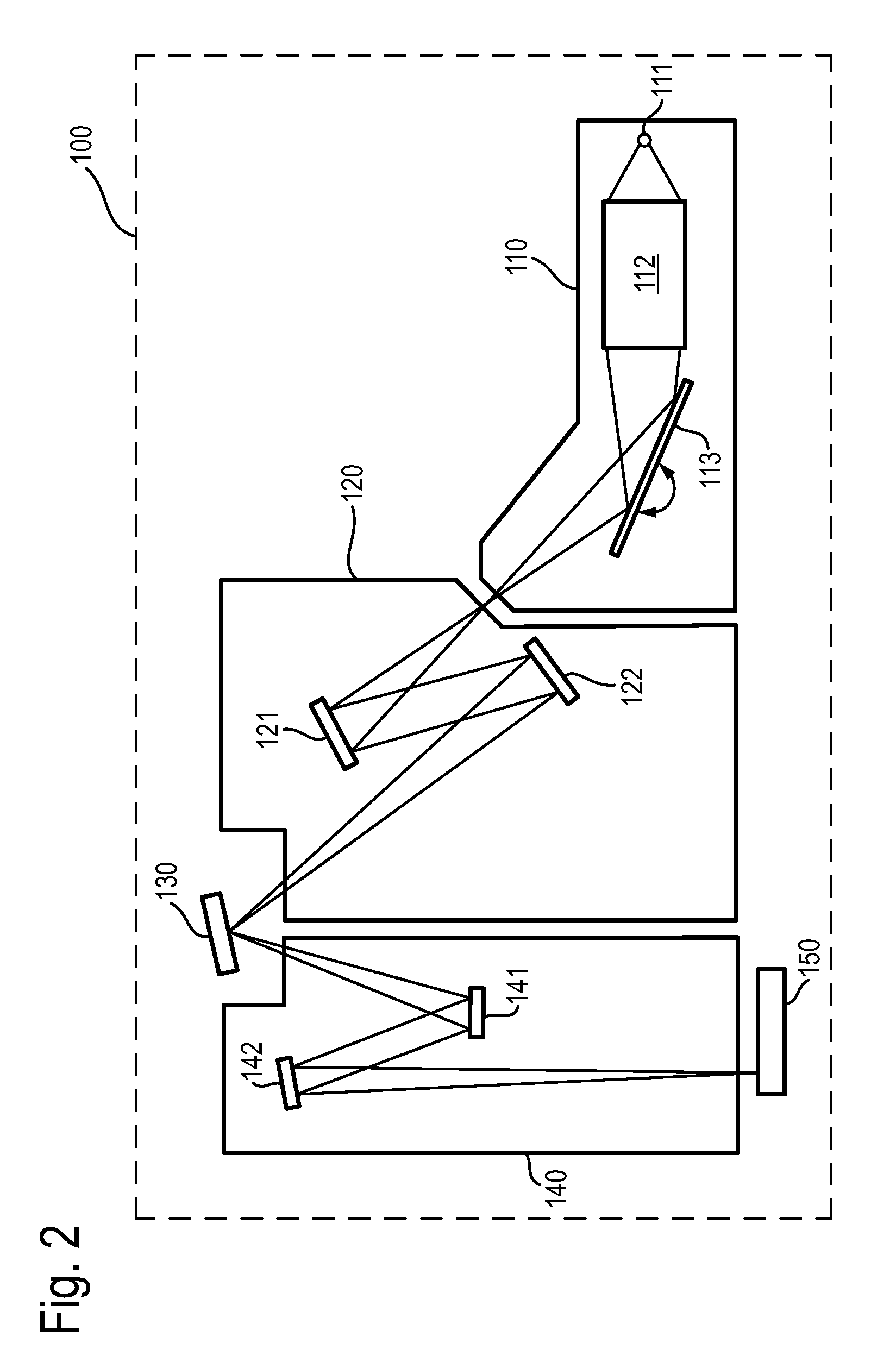
[0018]FIG. 2 illustrates schematically an embodiment of an EUV lithography apparatus;

[0019]FIGS. 3a, b illustrate schematically the bonding of a mirror or lens in a mounting;

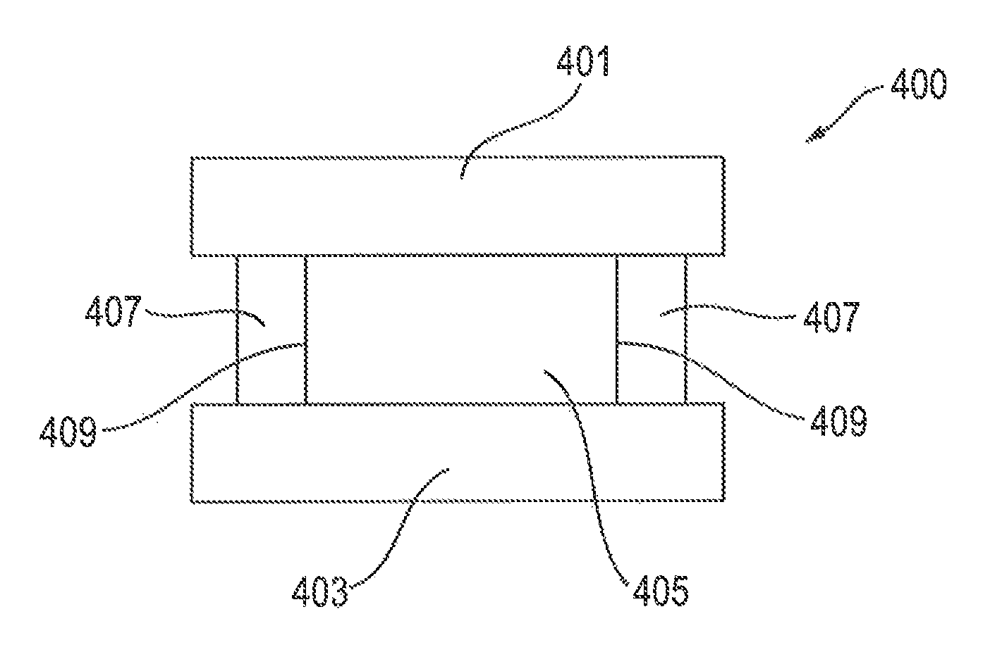
[0020]FIG. 4 illustrates schematically an embodiment of a component of adhesively bonded parts with protective layer;

[0021]FIG. 5 illustrates schematically a scale adhesively bonded to a mounting with protective layer;

[0022]FIG. 6 illustrates schematically a scale adhesively bonded to a mounting without protective layer;

[0023]FIG. 7 illustrates the impact of a protective layer on an adhesively bonded EUV mirror; and

[0024]FIG. 8 illustrates the impact of a protective layer on an adhesively bonded UV mirror.

DETAILED DESCRIPTION

[0025]FIG. 1 shows schematically a UV lithography apparatus 1. The UV...


PUM

PropertyMeasurementUnit
ultraviolet wavelength rangeaaaaaaaaaa
wavelengthaaaaaaaaaa

Abstract

To improve the bonding of two parts (401, 403) of a component (400) of an EUV or UV lithography apparatus such that the probability of occurrence of additional stress over time in the bonded parts (401, 403) is lessened, a component (400) of an EUV or UV lithography apparatus comprising two parts (401, 403) bonded to each other by adhesive material (405) is proposed, wherein the adhesive material (405) is coated with a protective layer (407) insulating the adhesive material (405) from the surrounding gas environment.

Description

CROSS REFERENCE TO RELATED APPLICATIONS[0001]This is a Continuation of International Application PCT / EP2009 / 005513, with an international filing date of Jul. 30, 2009, which was published under PCT Article 21(2) in English, and the entire contents of which are hereby incorporated by reference.FIELD AND BACKGROUND OF THE INVENTION[0002]The present invention relates to a component of an EUV or UV lithography apparatus comprising two parts bonded to each other by adhesive material, as well as to a projection system for an EUV or UV lithography apparatus and an EUV or UV lithography apparatus comprising such a component. The present invention further relates to a method for producing such a component.[0003]EUV lithography apparatuses, i.e. lithography apparatuses working in an extreme ultraviolet wavelength range of approximately 1 nm to 20 nm, as well as UV lithography apparatuses, i.e. lithography apparatuses working in an ultraviolet wavelength range of approximately 20 nm to 400 nm ...

Claims


Application Information

Patent Timeline
Patent Type & Authority Patents(United States)
IPC IPC(8): G03B27/52G03F7/20G03B27/68B29D11/00G03F1/38B82Y10/00B82Y40/00G02B7/00G03F1/00G03F1/24
CPCG03F7/70916B29D11/0073B82Y10/00B82Y40/00G02B7/00G03F1/14G03F1/24G03F1/38G03F7/70783G03F7/70808G03F7/70825G03F7/70841G21K2201/067Y10T156/10G03F1/62
Inventor CHUNG, HIN YIU ANTHONY
Owner CARL ZEISS SMT GMBH
Why Eureka
Try Eureka