Misfire prevention water agitator system and method

a technology of misfire prevention and water agitator, which is applied in the direction of machines/engines, combustion air/fuel air treatment, lighting and heating apparatus, etc., can solve the problems of engine misfire, reduced density of charge air, and puddles in the end tank may form or grow rapidly, so as to prevent water condensation, minimize spark retardation, and improve fuel economy

Active Publication Date: 2015-11-10
FORD GLOBAL TECH LLC
View PDF14 Cites 4 Cited by
  • Summary
  • Abstract
  • Description
  • Claims
  • Application Information

AI Technical Summary

Benefits of technology

[0004]Smaller displacement turbo charged engines may be used in bigger vehicles to improve fuel economy. The hot compressed air from a compressor becomes cooler in a charge air cooler (CAC) to minimize spark retard. With hot humid air moisture may condense out in a charge air cooler if it is cooled below the dew point. It has been measured that on a humid day some engines can condense enough water to form a puddle in the bottom of the charge air cooler outlet tank while cruising at 70 mph for 60 min. One measurement showed a rate of puddle accumulation of 120 cc / 60 min. In addition, if a driver goes into wide open pedal for, only 1 to 2 seconds, and then backs off the accelerator, a puddle in the end tank may form or grow rapidly. The engine can misfire if a big puddle is ingested at once during hard acceleration. For example, misfire has been shown to occur for water ingestion rates of greater than 20 cc / sec. This is not acceptable because the engine will not provide the power demanded. In addition, if the fuel injectors of the misfiring cylinders continue to inject fuel, the catalytic converter brick substrate can melt down from excessive heat.
[0005]Embodiments in accordance with the present disclosure may be used to prevent water condensation, and also to prevent water ingestion at rates high enough to cause misfire.
[0006]Embodiments may provide a drain tube at a location in the charge air cooler outlet tank where condensation may have a tendency to collect, and where the water condensate may puddle up. Embodiments may arrange an expansion chamber in line with the drain tube to collect the water. The expansion chamber may act as a water agitator to slow down the puddle ingestion into the engine through the drain tube. In addition, a valve may be disposed at an inlet to provide an agitating jet of the intake air to the water in the chamber. In this way, the valve may aid in atomizing the water into the intake air stream before it is passed through the intake manifold and into the combustion chamber. In this way, the condensate from the charge air cooler will be directed to the intact manifold of the engine in a controlled and measured way. In this way the engine will then be much less likely to misfire due to water ingestion.

Problems solved by technology

However, the compression of the intake air tends to heat it which tends to reduce the density of this charge air.
In addition, if a driver goes into wide open pedal for, only 1 to 2 seconds, and then backs off the accelerator, a puddle in the end tank may form or grow rapidly.
The engine can misfire if a big puddle is ingested at once during hard acceleration.
This is not acceptable because the engine will not provide the power demanded.
In addition, if the fuel injectors of the misfiring cylinders continue to inject fuel, the catalytic converter brick substrate can melt down from excessive heat.

Method used


Image

  • Misfire prevention water agitator system and method
  • Misfire prevention water agitator system and method
  • Misfire prevention water agitator system and method

Examples


Embodiment Construction

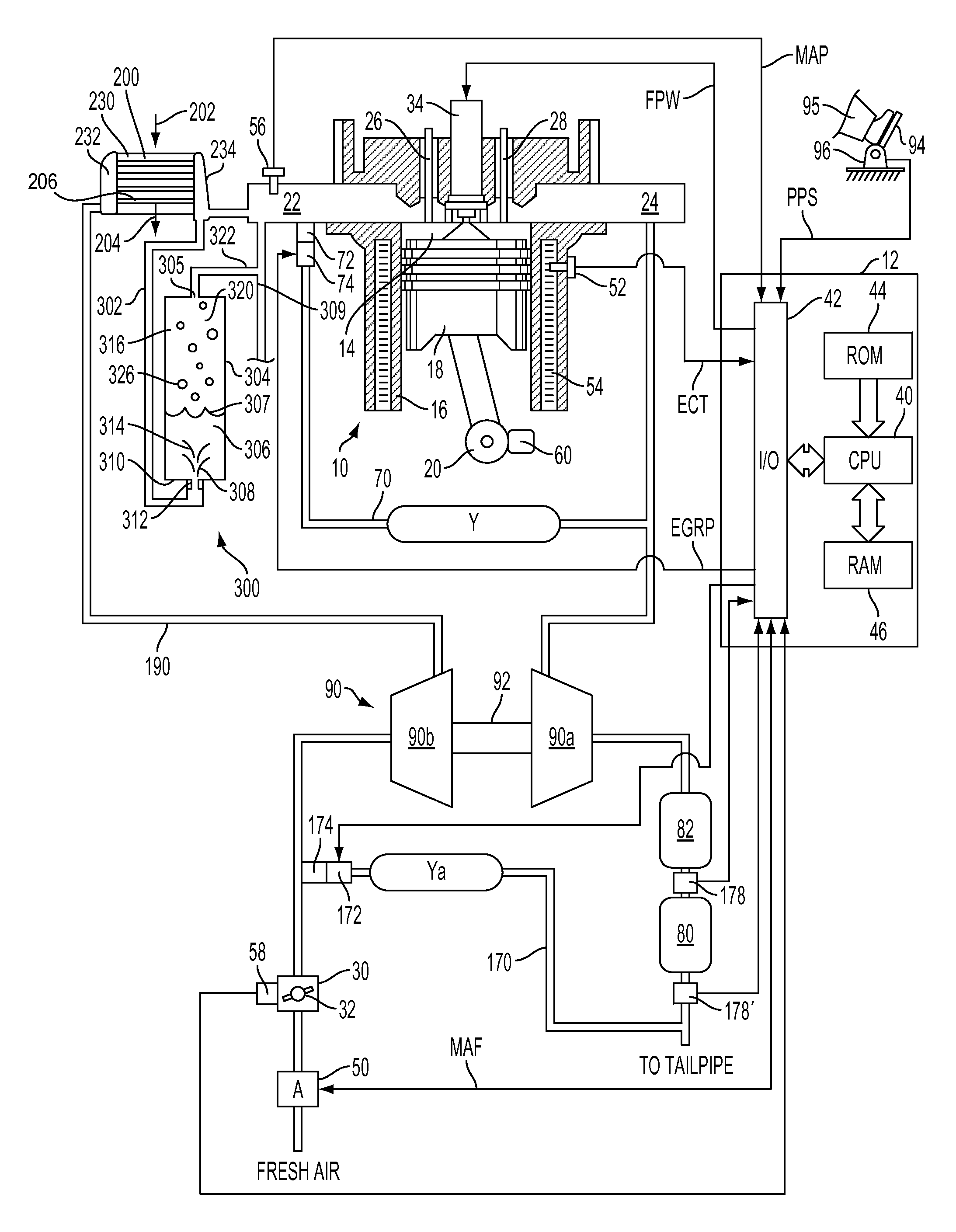
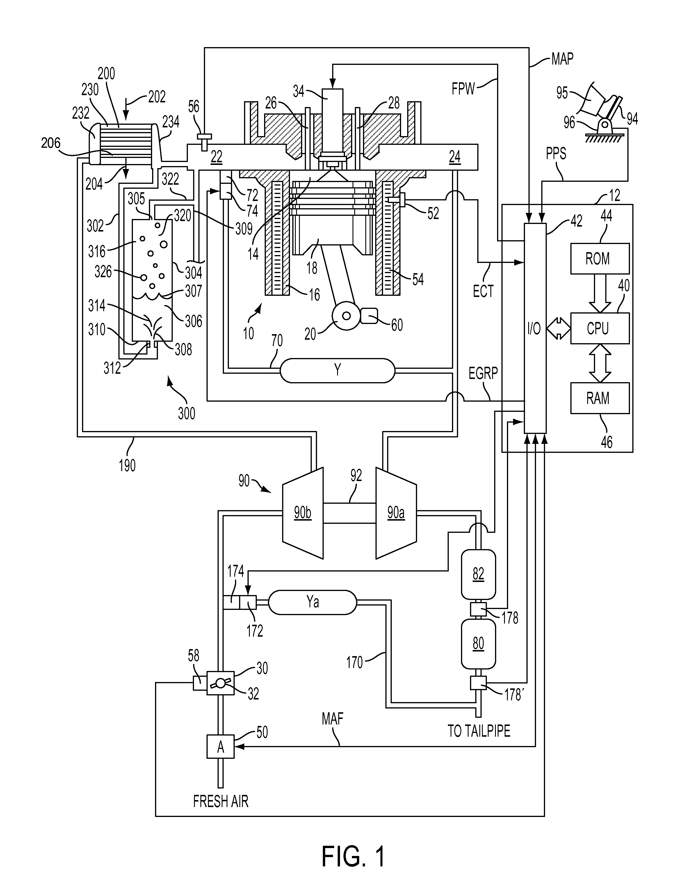
[0016]FIG. 1 is a schematic diagram, not to scale or accurately proportioned, showing an example of an engine system, for example, an engine system generally at 10. The engine system 10 may be a diesel engine, or a gasoline spark-ignition engine, or other type of engine that may utilize various components in accordance with the present disclosure. Specifically, internal combustion engine 10 comprises a plurality of cylinders, one cylinder of which is shown in FIG. 1. Engine 10 is controlled by electronic engine controller 12. Engine 10 includes combustion chamber 14 and cylinder walls 16 with piston 18 positioned therein and connected to crankshaft 20. Combustion chamber 14 communicates with an intake manifold 22 and an exhaust manifold 24 via respective intake valve 26 and exhaust valve 28.

[0017]Intake manifold 22 communicates with throttle body 30 via throttle plate 32. In one embodiment, an electronically controlled throttle can be used. In one embodiment, the throttle is electro...


PUM


Abstract

A misfire prevention water agitator system and method are disclosed. The system may include a boosted engine having a charge air cooler arranged in an engine intake passage downstream of a compressor and upstream of an intake manifold. The system may also include a bypass coupling an outlet tank of the charge air cooler with the intake manifold, the line including an agitator mounted within 45 degrees of vertical.

Description

CROSS REFERENCE TO RELATED APPLICATIONS[0001]The present application claims priority to U.S. Provisional Patent Application No. 61 / 648,008 filed on May 16, 2012, the entire contents of which are incorporated herein by reference for all purposes.FIELD[0002]The present application relates to methods and systems for controlling an ingestion rate of charge air cooler condensate by an engine, and specifically methods and systems wherein the condensate is passed to a container and then agitated with intake air while in the container in order to introduce the condensate in the intake air to be ingested at below a predetermined rate.BACKGROUND AND SUMMARY[0003]Many internal combustion engines include turbochargers, or superchargers configured to force more air mass into an engine's intake manifold and combustion chamber by compressing intake air with a compressor driven by a turbine disposed to capture energy from the flow of the engine exhaust gas. However, the compression of the intake ai...

Claims


Application Information

Patent Timeline
Patent Type & Authority Patents(United States)
IPC IPC(8): F02B33/00F02M25/028F28F13/12F02B33/44F02B29/04F02M25/07F02M35/16
CPCF02B29/04F02B29/0468F02M25/028F02M25/0707F02M35/161Y02T10/121Y02T10/146F02M26/05Y02T10/12
Inventor YAMADA, SHUYA SHARK
Owner FORD GLOBAL TECH LLC
Why Eureka
Try Eureka