Spot-array imaging system for maskless lithography and parallel confocal microscopy

a technology of confocal microscopy and imaging system, which is applied in the direction of material analysis through optical means, instruments, photomechanical equipment, etc., can solve the problem that the projection lens cannot achieve stringent optical aberration tolerances, and achieve optimal radiation intensity and polarization control, optimal correction of system point-imaging performance for each individual

Active Publication Date: 2015-11-17
JOHNSON KENNETH C
View PDF31 Cites 37 Cited by
  • Summary
  • Abstract
  • Description
  • Claims
  • Application Information

AI Technical Summary

Benefits of technology

[0017]The tradeoff between challenging microlens requirements and stringent projection lens requirements can be circumvented by employing micro-optics upstream of the projection lens to not only separate the radiation into discrete source spots, but to also compensate for imperfect imaging performance of the projection lens. This can be done in several ways: First, the source spots need not be focused through a common plane; they can be focused through a curved focal surface to compensate for any field curvature of the projection lens and ensure that the spot array is imaged onto a flat image plane. Second, the source spots need not be distributed on a uniform periodic

Problems solved by technology

Second, the source spots need not be distributed on a uniform periodic grid; they can be distributed non-uniformly to compensate for image distortion of the projection lens so that the projected image of the spot array forms a uniform periodic grid.
Third, the projecti

Method used


Image

  • Spot-array imaging system for maskless lithography and parallel confocal microscopy
  • Spot-array imaging system for maskless lithography and parallel confocal microscopy
  • Spot-array imaging system for maskless lithography and parallel confocal microscopy

Examples


embodiment

EUV Embodiment

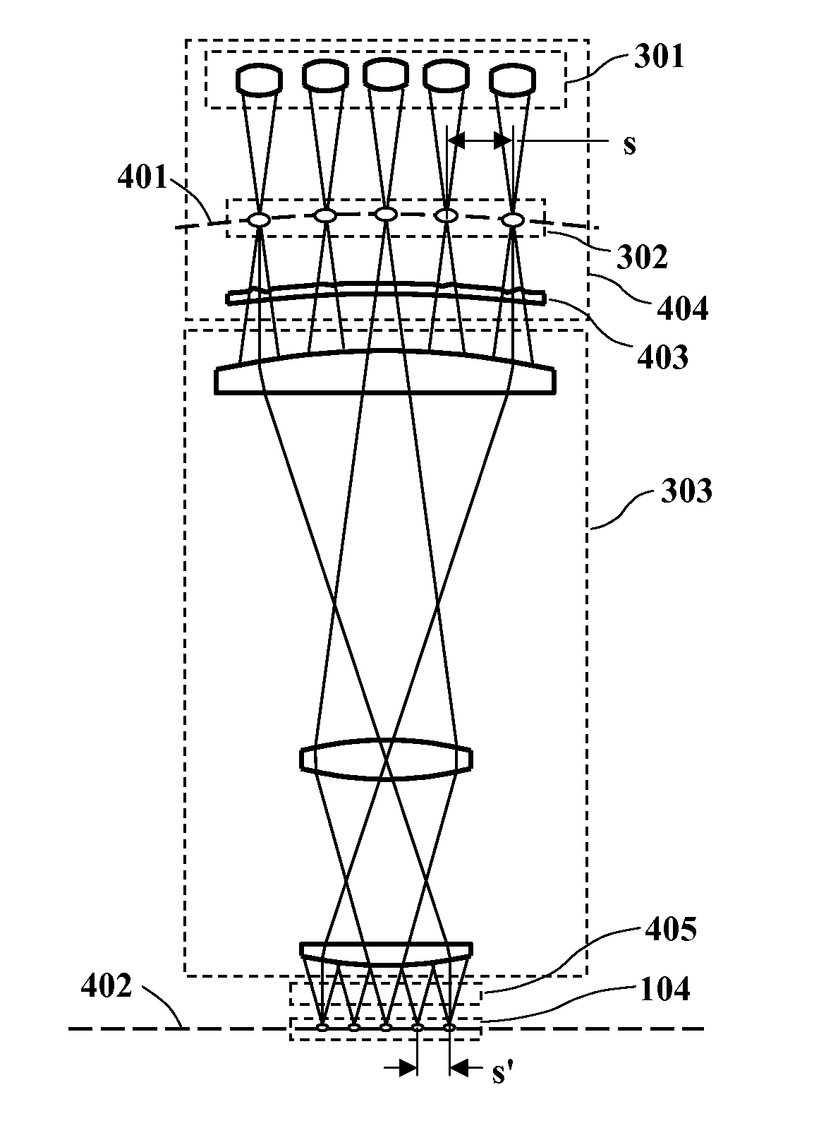
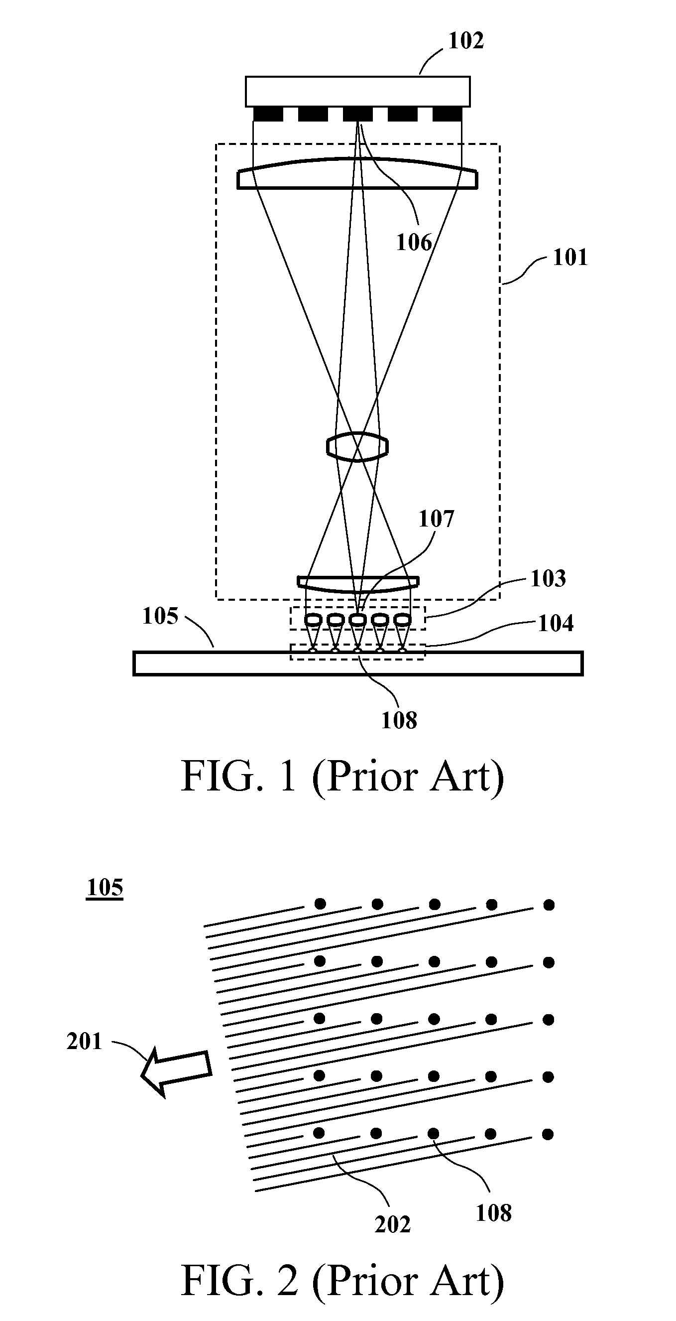
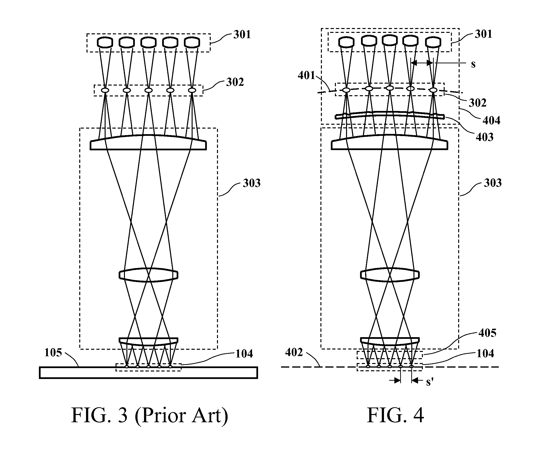
[0095]FIGS. 1, 3 and 4 illustrate the projection lens schematically as a dioptric (refractive) system, but it could more generally comprise a catoptric (reflective) or catadioptric (refractive and reflective) system. (The term “lens” is used generically to denote refractive and / or reflective imaging systems.) In particular, the invention would be applicable to extreme ultraviolet (EUV) lithography systems in which the projection optics consist only of mirrors. FIG. 15 illustrates a possible design configuration for EUV spot-generation optics, in cross-section. This particular embodiment could operate at a wavelength of 13.5 nm.

[0096]The EUV microlenses are molybdenum (Mo) zone-plate lenses such as lens 1501, shown in cross-section in FIG. 15 and in plan view in FIG. 16 or FIG. 17. The lenses are supported on a thin silicon (Si) substrate 1502, which is formed on top of a microchannel plate 1503. The lens form for this embodiment is illustrated in FIG. 16. Alternatively...


PUM


Abstract

In a scanned-spot-array lithography system, a modulated array of radiant-energy source spots is imaged by a projection lens onto a printing surface, which is scanned in synchronization with the spot modulation to print a synthesized, high-resolution raster image. Similarly, in a scanned-spot-array microscopy system, an array of radiant-energy source spots is imaged by a projection lens onto an inspection surface, and radiation reflected from or transmitted through the image spots is collected and detected to acquire a synthesized, high-resolution raster image of the surface. In either case, the spot-generation optics can be configured to counterbalance and neutralize imperfect imaging characteristics of the projection lens, enabling perfectly flat-field, distortion-free, and aberration-free point imaging of the entire spot array. The spot-generation optics can also be further configured to achieve narrow-band achromatization of the optical system, and to optimally control the intensity and polarization characteristics of the image-plane radiation.

Description

CROSS-REFERENCE TO RELATED APPLICATIONS[0001]This application claims the benefit under 35 U.S.C. §119(e) of the following five applications, all of which name Kenneth C. Johnson as the inventor, and all of which are incorporated by reference in their entirety for all purposes:[0002]U.S. Provisional Patent Application No. 61 / 498,427, filed Jun. 17, 2011 for “Scanned-Spot-Array Optical Lithography”;[0003]U.S. Provisional Patent Application No. 61 / 521,684, filed on Aug. 9, 2011 for[0004]“Scanned-Spot-Array Optical Lithography”;[0005]U.S. Provisional Patent Application No. 61 / 525,125, filed on Aug. 18, 2011 for[0006]“Spot-Array Imaging System for Maskless Lithography and Parallel Confocal Microscopy”;[0007]U.S. Provisional Patent Application No. 61 / 531,981, filed on Sep. 7, 2011 for[0008]“Spot-Array Imaging System for Maskless Lithography and Parallel Confocal Microscopy”; and[0009]U.S. Provisional Patent Application No. 61 / 549,158, filed Oct. 19, 2011 for “Spot-Array Imaging System for...

Claims


Application Information

Patent Timeline
IPC IPC(8): G03F7/20G01N21/88G01B9/04G02B21/00
CPCG02B21/002G03F7/70275G02B21/0036G01B9/04G03F7/70308G01N21/8806G03F7/70191G01N21/8803G02B21/0024G02B21/0052G01N21/95623G02B5/1814G02B5/1871G02B27/0031G02B27/1006G02B27/141G02B27/4233G03F7/70291G03F7/70391
Inventor JOHNSON, KENNETH C.
Owner JOHNSON KENNETH C
Why Eureka
Try Eureka