
Image analysis system and methods for IR optics

a technology of image analysis and optics, applied in the field of optics measurement devices, can solve the problems of limited instrument flexibility, insufficient sampling, and the duration of image scanning methods, and achieve the effect of minimizing the ir background

Active Publication Date: 2015-12-22
OPTIKOS CORP
View PDF14 Cites 7 Cited by
  • Summary
  • Abstract
  • Description
  • Claims
  • Application Information

AI Technical Summary

Benefits of technology

The system enables accurate and efficient measurement of IR optical components' performance by minimizing IR background interference and thermal noise, allowing for precise MTF determination and improved optical system characterization.

Problems solved by technology

The major disadvantage is that these methods require the simultaneous manipulation of sources and detectors, which limits instrument flexibility.
A drawback to image scanning methods is the duration of scan.
Insufficient sampling can significantly affect the accuracy of the MTF.
The drawbacks of video methods are inherent in the design of electronic solid state arrays.
However, the relay optics must be very high quality, must have a very high numerical aperture to capture the entire output of fast lenses or systems working at high off-axis angles, and should be essentially diffraction limited to not impact the measured MTF.
Pixel to pixel crosstalk, both optical and electrical, tend to increase the apparent image size and affect the measured MTF.
The accuracy of the computed MTF is limited by the level of digitizing.
Eight-bit video MTF systems are less accurate than conventional scanning systems.
In addition, since phase measuring interferometers have limited wavefront sampling capabilities, the wavefront should be fairly well corrected.
Lenses with excessive wavefront errors are difficult to measure with interferometers.
However, measurement in the far IR region of the spectrum (FWIR), between about 8-15 micrometers, whether using scanning or video detection, is not without problems.
Despite the use of sensitive IR detectors and high temperature blackbodies, the most significant challenge facing IR measurements is the signal / noise ratio.
Thus, the presence of background IR in the field of view of the detector is a very serious problem for MTF calculations if not properly managed.

Method used


Image

  • Image analysis system and methods for IR optics
  • Image analysis system and methods for IR optics
  • Image analysis system and methods for IR optics

Examples


Embodiment Construction

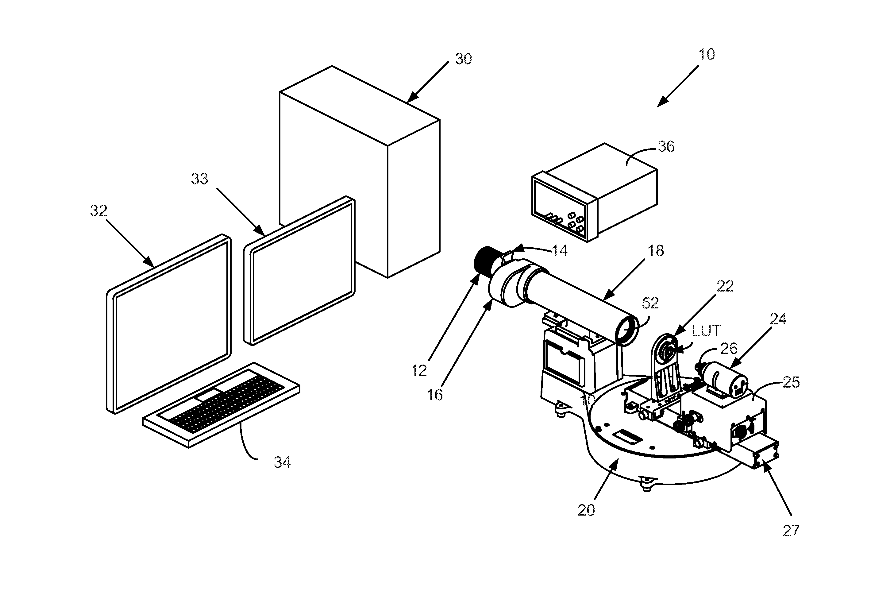
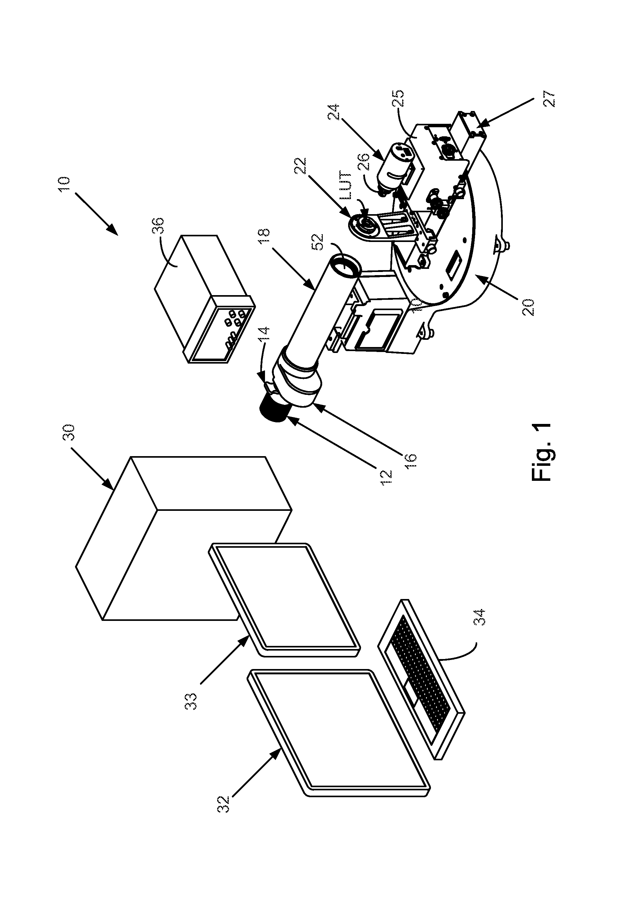
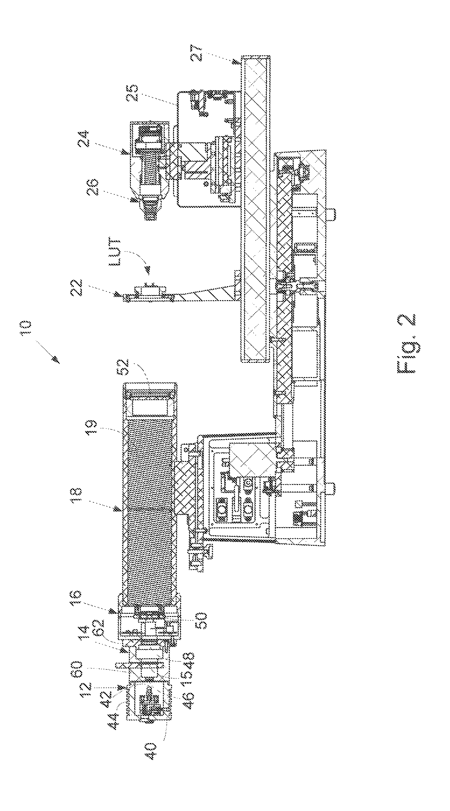
[0052]The present invention is a video-based metrology system for accurately measuring optical performance characteristics of optical systems designed to operate in the long-wave infrared (LWIR) waveband of the spectrum. As will be seen, the inventive system compensates for the time-varying DC offset introduced by the video sensor it employs and also for unwanted background IR that may be present in its optical measurement path during a measurement cycle. Thermal management features are provided in the system to reduce the presence of unwanted IR background radiation generated by the system itself, reduce the amount of ambient IR that may enter the measurement path open to its surrounding environment, minimize heat transfer at interfaces between its IR source and subassemblies downstream of the source, cool system housings passively, and reflect unwanted IR radiation from propagating from the source to downstream elements involved in measurements.

[0053]Referring now to FIGS. 1 and 2...


PUM

PropertyMeasurementUnit
diameteraaaaaaaaaa
color temperatureaaaaaaaaaa
operating wavelengthaaaaaaaaaa

Abstract

A system for quickly measuring and displaying in real-time a variety of performance characteristics of IR optical components such as lenses, or the like. The system is video based and is under the control of a computer which uses a windowing software program to provide the user with a graphical user interface by which the various components of the system and test lenses may be characterized and operated on through functions available via the interface. The system has features for compensating for the presence of IR background radiation that may be present during a measurement cycle and for drift in the video imager. Thermal management features are included to minimize IR background.

Description

BACKGROUND OF THE INVENTION[0001]1. Field of the Invention[0002]This invention, in general, relates to optics measurement devices and, in particular, to a real-time optic testing system for quickly performing two-dimensional image analyses on an IR test lens or the like, including the determination of its modulation transfer functions (MTFs).[0003]2. Background of the Prior Art[0004]Today's new technologies for designing and producing complex, high quality IR optical systems require optic measurement equipment that is sophisticated, flexible and accurate.[0005]Often this is achieved by measuring the modulation transfer function (MTF) of an optic, a measure of the ability of an optical system to transfer various levels of detail from object to image. Performance here is measured in terms of contrast (degrees of gray), or of modulation, produced for a perfect source of that detail level. MTF is like other transfer functions used in metrology where a response (output) is related to an ...

Claims


Application Information

Patent Timeline
Patent Type & Authority Patents(United States)
IPC IPC(8): G01N21/35G01M11/02
CPCG01M11/0207G01N21/35G01M11/0292
Inventor ORBAND, DANIEL
Owner OPTIKOS CORP
Learn More