Supercharge Your Innovation With Domain-Expert AI Agents!

Outboard sealing system for a heavy-duty vehicle wheel end assembly

a technology for heavy-duty vehicles and end caps, which is applied in the direction of engine components, mechanical equipment, transportation and packaging, etc., can solve the problems of not always providing effective seals, affecting the performance of the engine, and enabling precise alignment of the hubcap, so as to reduce the flow of lubricant and reduce corrosion.

Active Publication Date: 2016-01-05
HENDRICKSON USA L L C
View PDF9 Cites 1 Cited by
  • Summary
  • Abstract
  • Description
  • Claims
  • Application Information

AI Technical Summary

Benefits of technology

The system effectively retains lubricant, prevents contamination, maintains bearing position during servicing, and reduces corrosion, thereby extending the life of the wheel end assembly and simplifying maintenance by minimizing leakage and damage risks.

Problems solved by technology

Therefore, the wheel end assembly must be sealed to prevent leakage of the lubricant, and also to prevent contaminants from entering the assembly, both of which could be detrimental to its performance.
Such hubcaps, while adequate for some applications, typically did not enable precise alignment of the hubcap with the axle spindle, and did not always provide effective seals.
Such flow away from the bearings and the hub and into the hubcap creates a greater potential for leakage of lubricant at the hubcap seal to occur.
In addition, the viscosity and the tackiness of the semi-fluid grease tends to cause the lubricant to remain in the hubcap when the vehicle is not operating, rather than flowing back to the bearings and the hub.
The amount of lubricant that is retained at the bearings is therefore undesirably reduced, which may undesirably impair the operation of the bearings and reduce bearing life.
Moreover, because the hubcap is occasionally removed from the hub by a technician during servicing of the wheel end assembly, semi-fluid grease that remains in the hubcap creates an inconvenience for the technician, as he or she must clean the lubricant out of the hubcap.
However, in the prior art, once the spindle nut assembly is removed, the outboard bearing lacks positive mechanical engagement With the outboard end of the hub, and may slide out of the outboard end of the hub during the disassembly process.
If the outboard bearing slides out of the hub, it may become damaged, and / or the remainder of the wheel end assembly may be exposed to contaminants, either one of which undesirably can reduce the life of the bearings.
In addition, if the outboard bearing slides out of the hub during the disassembly process, or alternatively during reassembly of the wheel end assembly, the outboard end of the hub may undesirably shift or tip radially relative to the axle spindle, which may crimp or kink the main seal on the inboard end of the hub, thereby undesirably causing possible damage to the main seal.
If the position of the spindle nut assembly does not create a sufficient clamp force on the bearings and any spacer, there may be excessive end play of the bearings, which in turn creates excessive axial end play of the wheel end assembly relative to the axle spindle, thereby allowing undesirable movement of the main seal that may reduce the life of the main seal and the bearings.
If the position of the spindle nut assembly creates a clamp force on the bearings and any spacer that is too high, the bearings may be effectively over-compressed, interfering with their rotation and causing them to possibly wear out prematurely.
Therefore, movement of the outboard bearing out of the hub during disassembly or reassembly of the wheel end assembly may result in contamination of the wheel end assembly, damage to components, and / or potential improper installation of the spindle nut assembly, all of which result in an undesirable increase in the time and cost associated with the servicing of the wheel end assembly.
However, these retainers typically have been an integral part of a certain type of spindle nut assembly, which is not readily separable from the hub.
Some of these spindle nut assemblies include retainers, which possess disadvantages associated with reassembly of the wheel end assembly.
For example, these retainers allow the outboard bearing to move somewhat, which creates the possibility that the outboard bearing may be out of position and / or not properly seated when the spindle nut assembly is tightened, thereby binding and thus damaging the bearing.
While the improved bearing retainer works satisfactorily for its intended function, it has been found that, under certain conditions during assembly of the retainer ring, the ring may contact and score the surface of the hub bore.
Scoring of the surface of the hub bore may impair the integrity of the hub surface, which may in turn reduce the ability of the above-described O-ring to provide an optimum seal, which in turn undesirably increases the potential for bearing lubricant to leak out of the wheel end assembly, and the potential for contaminants to enter the assembly.
More particularly, when a heavy-duty vehicle travels over roads and there is moisture on the road surface, road spray may be generated.
The accumulation of moisture and salt and / or other chemicals at the interface between the hubcap and the hub may cause galvanic corrosion cells to form.
These corrosion cells then tend to propagate, and if there is significant propagation of corrosion cells at the interface between the hubcap and the hub, it may impair the seal between the hubcap and the hub.
In the event the seal is impaired, the potential for bearing lubricant to leak out of the wheel end assembly, and the potential for contaminants to enter the assembly, is undesirably increased.
In addition, if the corrosion cells continue to propagate, they may spread to components such as the axle spindle nut and / or the bearings, which may reduce the life of such components.

Method used


Image

  • Outboard sealing system for a heavy-duty vehicle wheel end assembly
  • Outboard sealing system for a heavy-duty vehicle wheel end assembly
  • Outboard sealing system for a heavy-duty vehicle wheel end assembly

Examples


Embodiment Construction

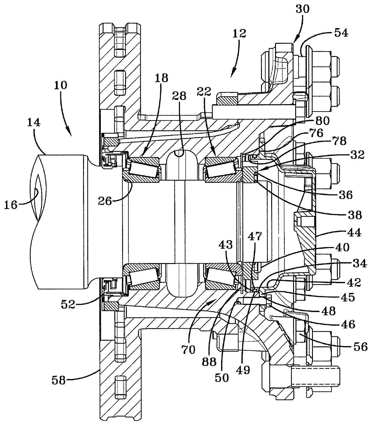
[0035]Turning to FIG. 1, in order to better understand the outboard sealing system of the present invention and the environment in which it operates, a prior art axle spindle and wheel end assembly for a heavy-duty vehicle is shown and now will be described. An axle 10 depends from and extends transversely across the trailer of a heavy-duty tractor-trailer (not shown). A typical heavy-duty tractor-trailer includes one or more non-drive axles 10 suspended from the trailer, with each of the axles having a wheel end assembly 12 mounted on each end of the axle. Since each of the ends of axle 10 and its associated wheel end assembly 12 are generally identical, only one axle end and wheel end assembly 12 will be described herein. Axle 10 includes a central tube (not shown), and an axle spindle 14 is integrally connected by any suitable means, such as welding, to each end of the central tube. The axle central tube generally is tubular-shaped and is formed with an internal cavity (not shown...


PUM


Abstract

An outboard sealing system cooperates with components of a heavy-duty vehicle wheel end assembly to retain lubricant in the assembly. The sealing system includes a seal that is disposed axially between an outboard bearing and a hubcap of a wheel end assembly. The seal also extends radially between an axle spindle nut and a surface of a bore formed in the hub of the wheel end assembly. The seal forms a barrier between the outboard bearing and the hubcap to reduce a flow of lubricant from a hub cavity into the hubcap. The sealing system retains lubricant in the wheel end assembly, prevents contaminants from entering the wheel end assembly, and retains the relative position of the outboard bearing in the hub during servicing. The sealing system preferably includes an additional barrier that reduces corrosion at the interface of the hubcap and an outboard face of the hub.

Description

CROSS-REFERENCE TO RELATED APPLICATIONS[0001]This application claims the benefit of U.S. Provisional Patent Application Ser. No. 61 / 740,129, which was filed on Dec. 20, 2012.BACKGROUND OF THE INVENTION[0002]1. Technical Field[0003]The invention relates to wheel end assemblies, and in particular to wheel end assemblies for heavy-duty vehicles, such as tractor-trailers. More particularly, the invention relates to an outboard sealing system for a heavy-duty vehicle wheel end assembly. Still more particularly, the invention is directed to a sealing system that includes a seal which cooperates with an axle spindle nut and a hub of the wheel end assembly. The seal is disposed between an outboard bearing and a hubcap of the wheel end assembly, and is formed with features that extend radially between the axle spindle nut and a bore of the hub of the wheel end assembly.[0004]The sealing system retains lubricant in the wheel end assembly, and particularly at the interface between the axle spi...

Claims


Application Information

Patent Timeline
Patent Type & Authority Patents(United States)
IPC IPC(8): B60C23/00B60B7/00
CPCB60B7/0013B60Y2200/142F16C33/7813F16J15/32F16J15/3204F16J15/3276F16C2326/02
Inventor WHITE, JAY D.DHARAIYA, DHAWAL
Owner HENDRICKSON USA L L C
Features
  • R&D
  • Intellectual Property
  • Life Sciences
  • Materials
  • Tech Scout
  • Unparalleled Data Quality
  • Higher Quality Content
  • 60% Fewer Hallucinations
Learn More