Underwater propelling device for underwater vehicle

a propelling device and underwater technology, applied in underwater equipment, special-purpose vessels, vessel construction, etc., can solve the problems of reducing the performance of the vehicle, deteriorating and losing the vehicle, and difficult to ensure, so as to reduce the friction between the rotor and the stator

Active Publication Date: 2016-01-05
ECOLE POLYTECHNIQUE FEDERALE DE LAUSANNE (EPFL)
View PDF11 Cites 26 Cited by
  • Summary
  • Abstract
  • Description
  • Claims
  • Application Information

AI Technical Summary

Benefits of technology

[0016]wherein the rotor is axially separated from the stator by a gap so as to permit the formation of a hydraulic film inside said gap, said hydraulic film being ad

Problems solved by technology

However, such miniature dimensions can increase the vulnerability of the underwater vehicles to debris intrusion or to fishing lines becoming tangled in the propeller of said vehicles, which could significantly reduce their performance and, in the worst case, lead to their deterioration and loss of the vehicle.
Additionally, it can be challenging to ensure that the moving parts of a propulsion system are water- and pressure proof with high reliability.
Dynamic seals around motor shafts can wear out quickly, particularly when exposed to suspended sand particles or other particulates in the water.
Exposed metal parts are also affected by corrosi

Method used


Image

  • Underwater propelling device for underwater vehicle
  • Underwater propelling device for underwater vehicle
  • Underwater propelling device for underwater vehicle

Examples


Embodiment Construction

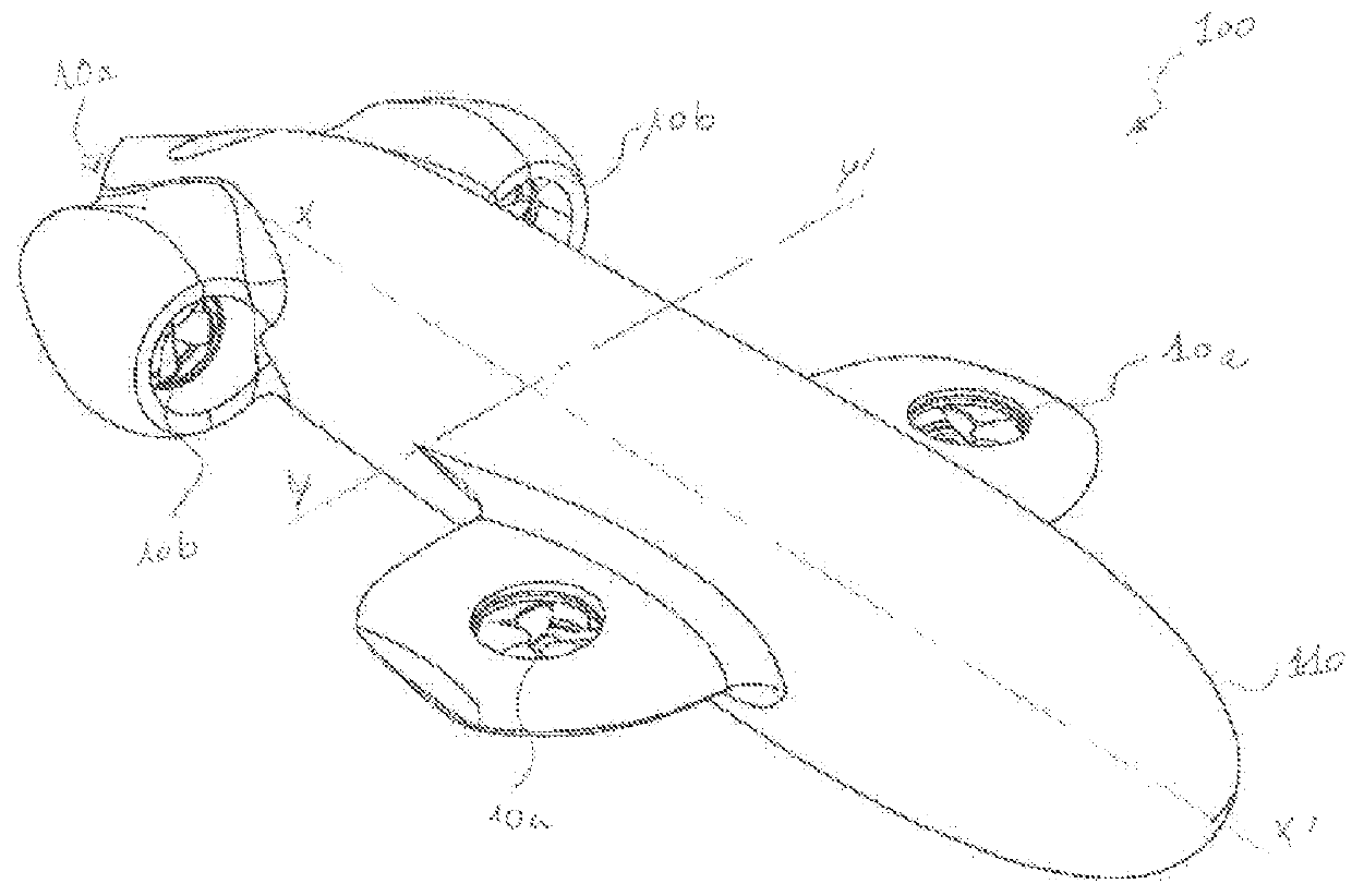
[0031]In reference to FIG. 1, there is shown a submarine vessel 100 having a body 110 that mounts five propelling devices 10a, 10b according to the present invention. Each propelling device is configured to provide a controlled thrust in either of two opposing directions, whereby the propelling devices can be controlled to cooperate to move the vessel in any desired direction. In particular, three propelling devices 10a are configured to provide a thrust along a direction perpendicular to a longitudinal axis XX′ of the body 110 and two propelling devices 10b are configured to provide a thrust along a direction parallel to said longitudinal axis XX′. The body 110 may advantageously have small dimensions. In particular, its length along the longitudinal axis XX′ may preferably be less than 1.5 meter and, more preferably, less than 80 cm.

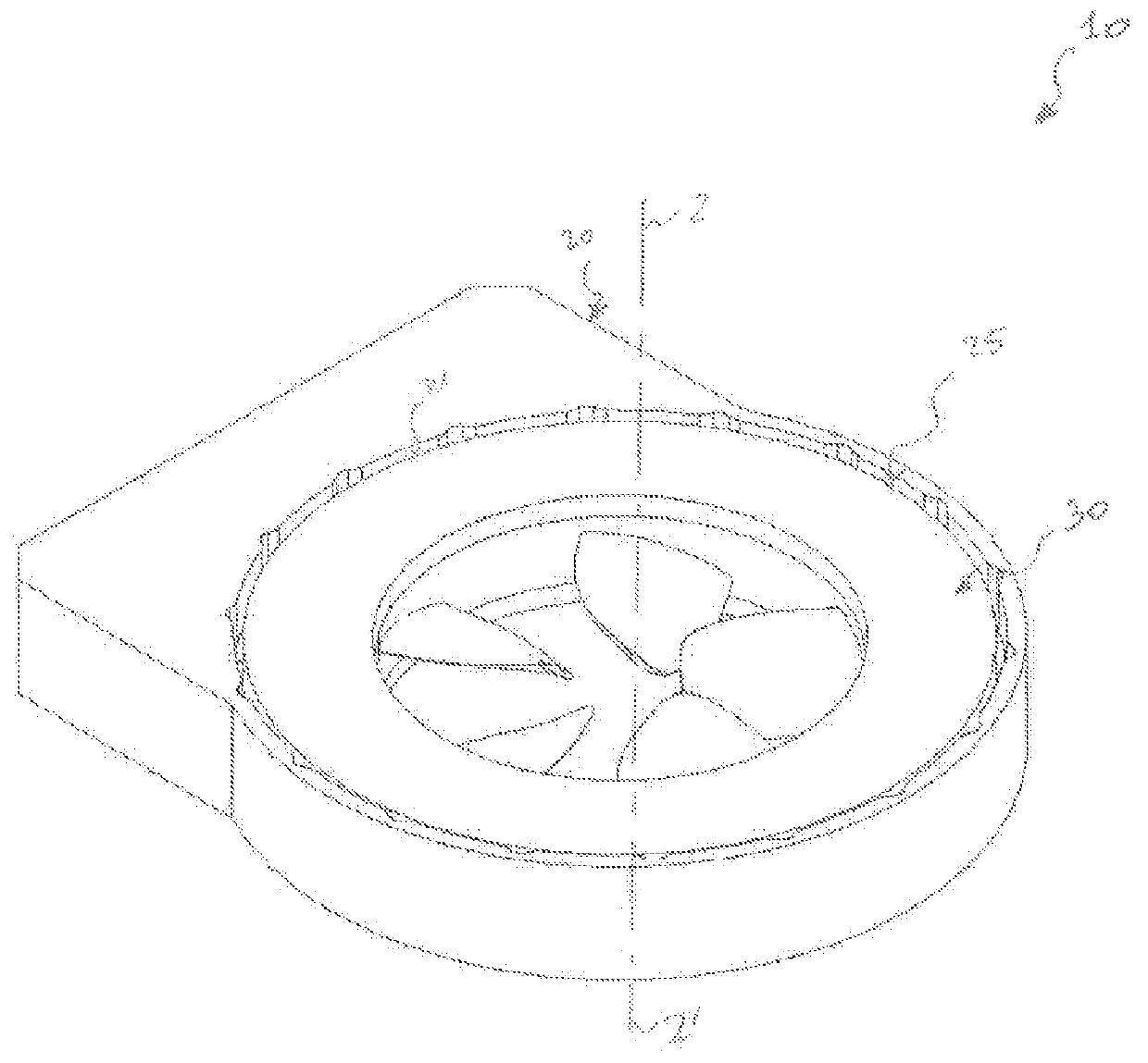
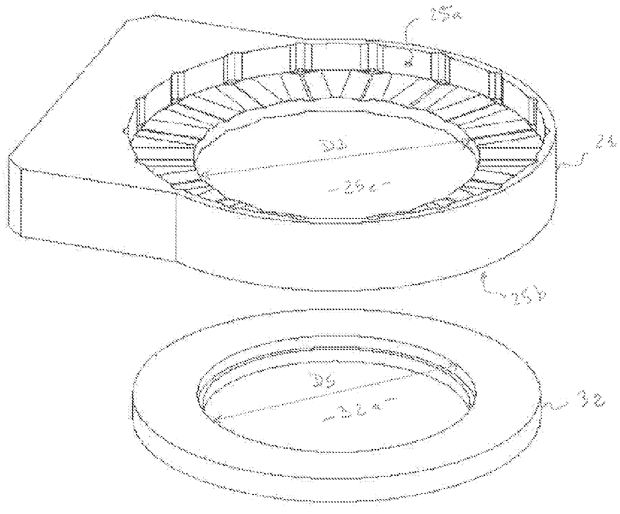
[0032]As shown in FIGS. 2 to 5, each propelling device 10 includes a stator assembly 20 securely fastened to the body 110 and a shaftless rotor assemb...


PUM


Abstract

The present invention relates to an underwater propelling device (10) i
    • a stator (20) comprising circumferential arrayed coils (35) and being adapted to generate a controlled electromagnetic field along an axial direction,
    • a shaftless propellant rotor (30) comprising:
      • at least two magnetized ring-shaped plates, respectively an upper magnetized plate (31) and a lower magnetized plate (32), coaxially spaced-apart along said axial direction and perpendicular thereto such that said circumferential arrayed coils (35) are positioned therebetween, each plate (31, 32) defining a central aperture (31a, 32a) and having a circumferential array of radially extended magnetized poles (34) embedded therein, said magnetized poles (34) generating a magnetic field which interacts with the electromagnetic field of the stator (20) so as to cause the rotation of said plates (31, 32) about a central axis (ZZ′) parallel to said axial direction,
      • at least one ring-shaped propeller (33) defined by its outer periphery and its inner periphery, said propeller being received inside the central apertures (31a, 32a) of said plates (31, 32) and fixedly secured thereto,
      • a plurality of propeller blades (35) projecting inward from the inner periphery of said propeller (33), said blades (35) producing a thrust along the central axis (ZZ′) when the plates (31, 32) rotate,
wherein the rotor (30) is axially separated from the stator (20) by a gap, preferably less than 3 mm, so as to permit the formation of a hydraulic film inside said gap, said hydraulic film being adapted to provide lubrication of the rotor, thus reducing friction between the rotor and the stator, and to transmit the axial thrust force of the rotor to the stator.

Description

FIELD OF THE INVENTION[0001]The present invention relates to an underwater propelling device for an underwater vehicle. More particularly, it concerns a propelling device with a light and simple structure that can be easily manufactured.[0002]The present invention relates also to an underwater vehicle equipped with such an underwater propelling device.BACKGROUND OF THE INVENTION[0003]Unmanned underwater vehicles are known for a long time. In particular, a toy submarine boat has been disclosed in the document U.S. Pat. No. 741,581. More recently, such vehicles have been used as drones for carrying out a variety of tasks in the underwater environment, e.g. pipeline surveys and investigations or military tasks. An example of such an application has been disclosed in the document WO 2014 / 113121.[0004]Unmanned underwater vehicles often have small or miniature dimensions so as to permit their easy handling and their storage inside limited space. However, such miniature dimensions can incr...

Claims


Application Information

Patent Timeline
IPC IPC(8): B63H21/17B63G8/08B63H5/15B63G8/00
CPCB63G8/08B63G8/001B63H21/17B63H5/15B63G2008/002B63G8/16B63H1/16B63H23/326F16C17/047F16C17/14B63H2001/165F16C2326/30B63H2023/005
Inventor SCHILL, FELIXBAHR, ALEXANDER
Owner ECOLE POLYTECHNIQUE FEDERALE DE LAUSANNE (EPFL)
Why Eureka
Try Eureka