Frequency modulated radar level gauging

a radar level gauge and frequency modulation technology, applied in the direction of engine lubrication, liquid/fluent solid measurement, reradiation, etc., can solve the problems of increasing the complexity and power consumption of the device, and less suitable for applications where power is required, so as to improve the sensitivity, improve the performance and reduce the energy demand of the radar level gauge

Active Publication Date: 2016-01-12
ROSEMOUNT TANK RADAR
View PDF20 Cites 2 Cited by
  • Summary
  • Abstract
  • Description
  • Claims
  • Application Information

AI Technical Summary

Benefits of technology

[0006]With regards to the above-mentioned desired properties of a radar level gauge, it is a general object of the present invention to enable improved performance of a radar level gauge by improving the sensitivity, and to reduce the energy demand of a radar level gauge by enabling a lower emitted power.
[0007]The present invention is based upon the realization that by configuring electronic components comprised in a radar level gauge to provide ordinarily undesirable effects, those undesirable effects will actually provide an added modulation, thereby enabling an increased sensitivity for the radar level gauge.
[0010]The modulation formed by the oscillation in the feedback loop enables an improved sensitivity without adding components, and thereby complexity to the radar level gauge. The improved sensitivity is achieved through providing the intermediate frequency signal at a higher frequency than normal. The intermediate frequency signal according to the present invention will comprise the frequency of the sinusoidal modulation and the harmonics of that frequency (i.e. integer multiples of the sinusoidal modulation frequency) plus the ordinary intermediate frequency. The higher frequency of the intermediate signal will suppress the leakage from electronics, waveguides and also decrease the impact of interference caused by objects in close proximity to the signal propagation device. The increased sensitivity may be as much as 10-20 dB.

Problems solved by technology

Although highly accurate, conventional FMCW systems (continuous as well as stepped) are relatively power hungry, making them less suitable for applications where power is limited.
However, such modulation typically requires added components, i.e. an additional oscillator and an adder, and will therefore increase the complexity and power consumption of the device.

Method used


Image

  • Frequency modulated radar level gauging
  • Frequency modulated radar level gauging
  • Frequency modulated radar level gauging

Examples


Embodiment Construction

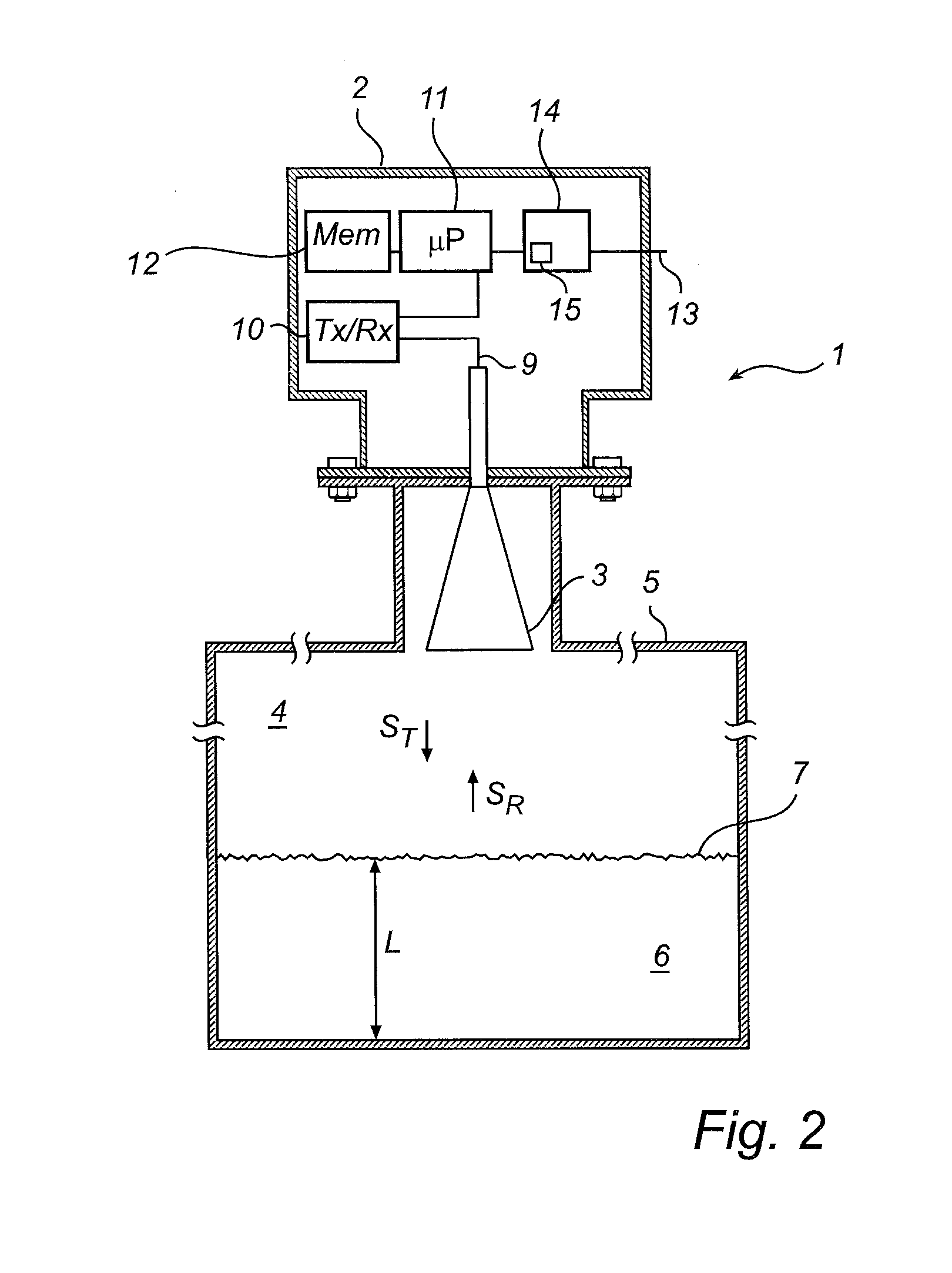
[0025]In the present description, embodiments of the present invention are mainly described with reference to a radar level gauge having a free propagating antenna for radiating and capturing an electromagnetic signal. It should be noted that this by no means limits the scope of the invention, which is equally applicable to other signal propagating devices, including other free propagating antennas such as a rod antenna, a patch antenna, a fixed or movable parabolic antenna or a conical antenna, and wave guides, such as a still pipe, a transmission line or a probe, such as a single-line probe (including a so-called Goubau probe), a twin-line probe or a coaxial probe.

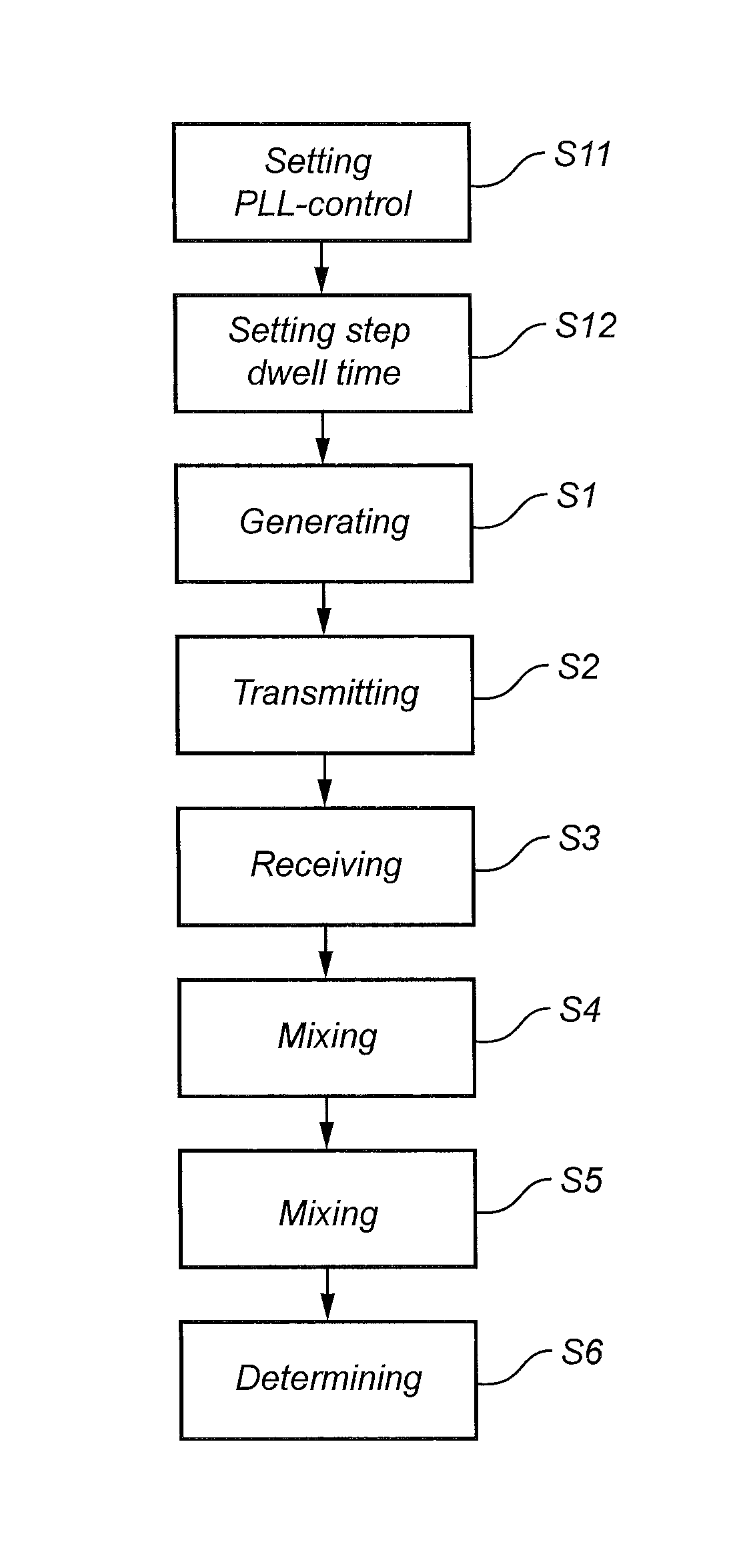
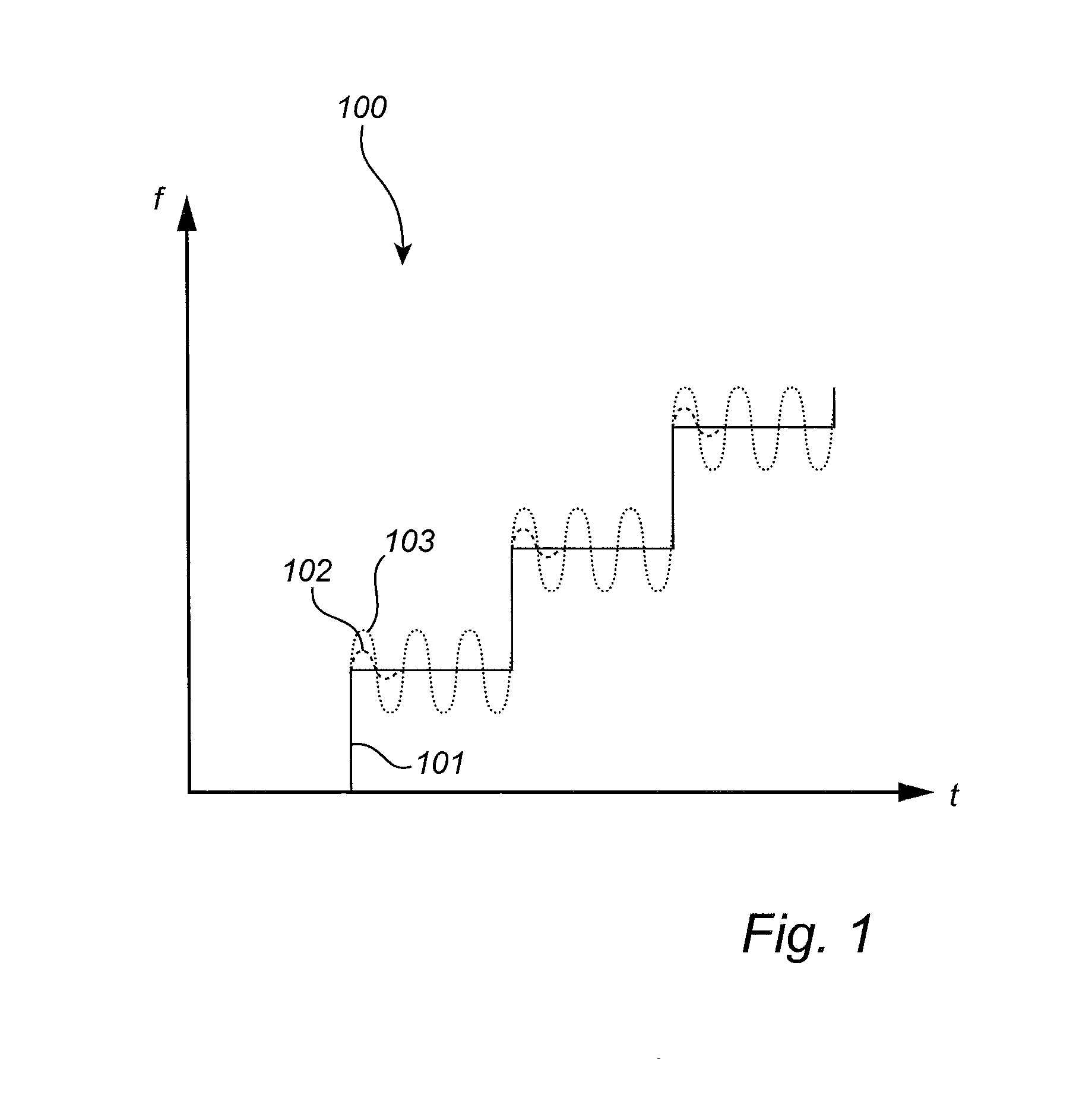
[0026]Further, in the following description, embodiments of the present invention are mainly described with reference to an FMCW radar level gauge using a stepped frequency sweep. It is noted that the present invention is advantageous in any sampled FMCW, such as a FMCW using a continuous frequency sweep, or even other t...


PUM


Abstract

A radar level gauge and a method for measurement of a distance to a surface of a product in a tank are disclosed. The radar level gauge comprises transceiver circuitry configured to transmit and receive electromagnetic signals, the transceiver circuitry comprises a frequency stabilizing feedback loop configured to generate the electromagnetic transmit signal in the form of a frequency sweep. The frequency stabilizing feedback loop is configured to generate an oscillation, forming a sinusoidal modulation of the frequency sweep. The radar level gauge further comprises a second mixer configured to mix an intermediate frequency signal and an integer multiple of the frequency of the sinusoidal modulation to provide an adjusted intermediate frequency signal, and processing circuitry configured to determine the distance based on the adjusted intermediate frequency signal.By providing a frequency sweep comprising a sinusoidal modulation, an improved sensitivity is achieved by the radar level gauge and method.

Description

FIELD OF THE INVENTION[0001]The present invention relates to a radar level gauge and method using electromagnetic waves to determine a distance to a surface of a product in a tank.BACKGROUND OF THE INVENTION[0002]Since radar level gauging was developed as a commercial product in the 1970's and 1980's, frequency modulated continuous wave (FMCW) has been the dominating measuring principle for high accuracy applications. An FMCW measurement comprises transmitting into the tank a signal which is swept over a frequency range in the order of a few GHz. For example, the signal can be in the range 9-11 GHz, or 24-27 GHz. The transmitted signal is reflected by the surface of the contents in the tank (or by any other impedance transition) and an echo signal, which has been delayed a certain time, is returned to the gauge. The echo signal is mixed with the transmitted signal to generate a mixer signal, having a frequency equal to the frequency change of the transmitted signal that has taken pl...

Claims


Application Information

Patent Timeline
Patent Type & Authority Patents(United States)
IPC IPC(8): G01S13/08G01F23/284G01S13/34
CPCG01F23/284G01S13/347
Inventor JIRSKOG, ANDERS
Owner ROSEMOUNT TANK RADAR
Why Eureka
Try Eureka