

Robust optical crimp connector
a technology of optical crimping and connectors, applied in the direction of optics, instruments, fibre mechanical structures, etc., can solve the problems of low tensile strength, easy damage to delicate assemblies, and fibers that may still be damaged
- Summary
- Abstract
- Description
- Claims
- Application Information
AI Technical Summary
Benefits of technology
Problems solved by technology
Method used
Image

Examples
Embodiment Construction
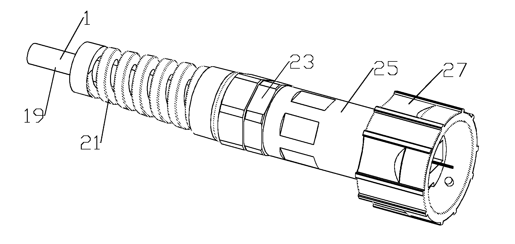
[0036]The inventor has recognized that, even if protected by a furcation tube, an optical fiber terminated in an LC connector has low pull strength due to the relatively weak plastic spring clips (retention tabs) typical of the LC connector interlock with the mating socket to which it is connected. Further, a typical optical fiber furcation tube may provide little or no resistance to damage from exceeding the minimum bend radius of the optical fiber or crushing of the furcation tube and optical fiber therewithin.
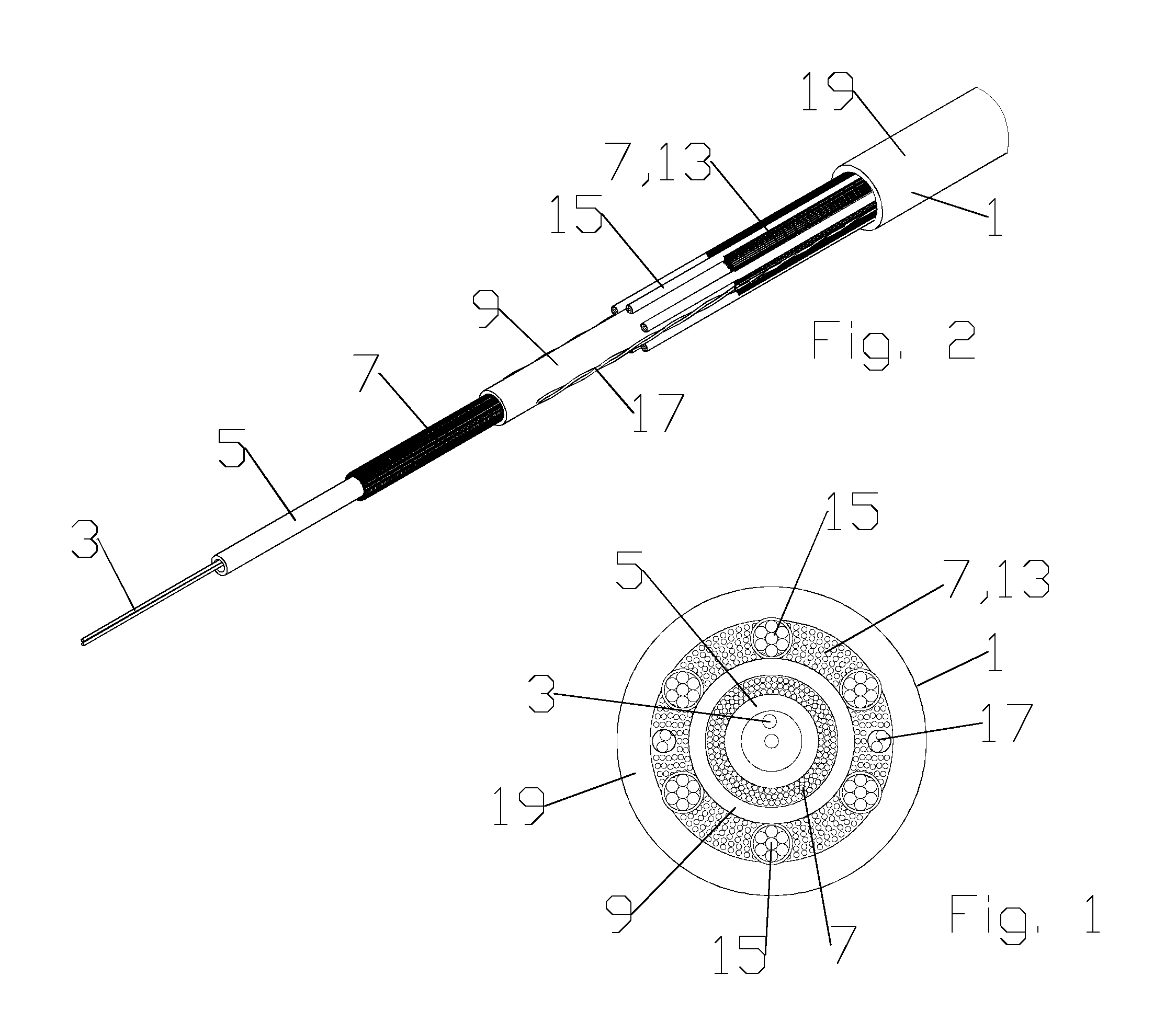
[0037]An armored optical cable 1 or furcation tube, for example as shown in FIGS. 1 and 2, includes the optical fibers 3 within the inner tube 5 and surrounding layer of aramid yarn 7. Further, the aramid yarn 7 is surrounded by an inner jacket 9, comprising a fiber sub-unit 11 / furcation tube. The fiber sub-unit 11 is further enclosed within an outer fiber layer 13 of aramid fibers and / or yarns that may be further reinforced with strength members 15 such as glass reinforced ...
PUM
 Abstract
Description
Claims
Application Information