
Heat-electricity combined production system that utilizes solar energy and geothermal heat

a production system and heat-electricity technology, applied in heat pumps, sustainable manufacturing/processing, lighting and heating apparatus, etc., can solve the problems of reducing the lifespan, low thermal efficiency, and inability to use geothermal heat as a primary energy source, and achieve the effect of improving energy efficiency

Active Publication Date: 2016-01-26
KOREA INST OF ENERGY RES
View PDF7 Cites 31 Cited by
  • Summary
  • Abstract
  • Description
  • Claims
  • Application Information

AI Technical Summary

Benefits of technology

Improves energy efficiency by reducing compressor load, enhancing thermal efficiency, and simplifying the heating system, while saving energy and reducing construction costs through the use of air as a heating medium and efficient cooling of solar cell heat.

Problems solved by technology

In particular, geothermal heat cannot be used as a primary energy source, however, if geothermal heat is used as a heat pump heat source having high energy efficiency, there is a very high possibility that geothermal heat will be used as building cooling and heating energy.
However, according to the related art, since heat is individually transferred from solar heat and geothermal heat and is used, thermal efficiency is not high.
In case of a geothermal heat pump system using geothermal heat, when the heat pump system operates for winter heating, a large load is applied to a compressor such that problems of frequent trouble of the compressor and reduction in the lifespan caused thereby may occur.
However, in most prior arts, there is a structure in which a single refrigerant is used and the installation of a cooling pipe for a flow path of the refrigerant is complicated.
However, in the above prior-art documents, additional power is required to flow heated air into the interior or to drive a blowing fan for discharging air in a separation space.

Method used


Image

  • Heat-electricity combined production system that utilizes solar energy and geothermal heat
  • Heat-electricity combined production system that utilizes solar energy and geothermal heat
  • Heat-electricity combined production system that utilizes solar energy and geothermal heat

Examples


Embodiment Construction

[0058]Exemplary embodiments of the present invention will be described in detail below with reference to the accompanying drawings. Like reference numerals in the drawings refer to like elements.

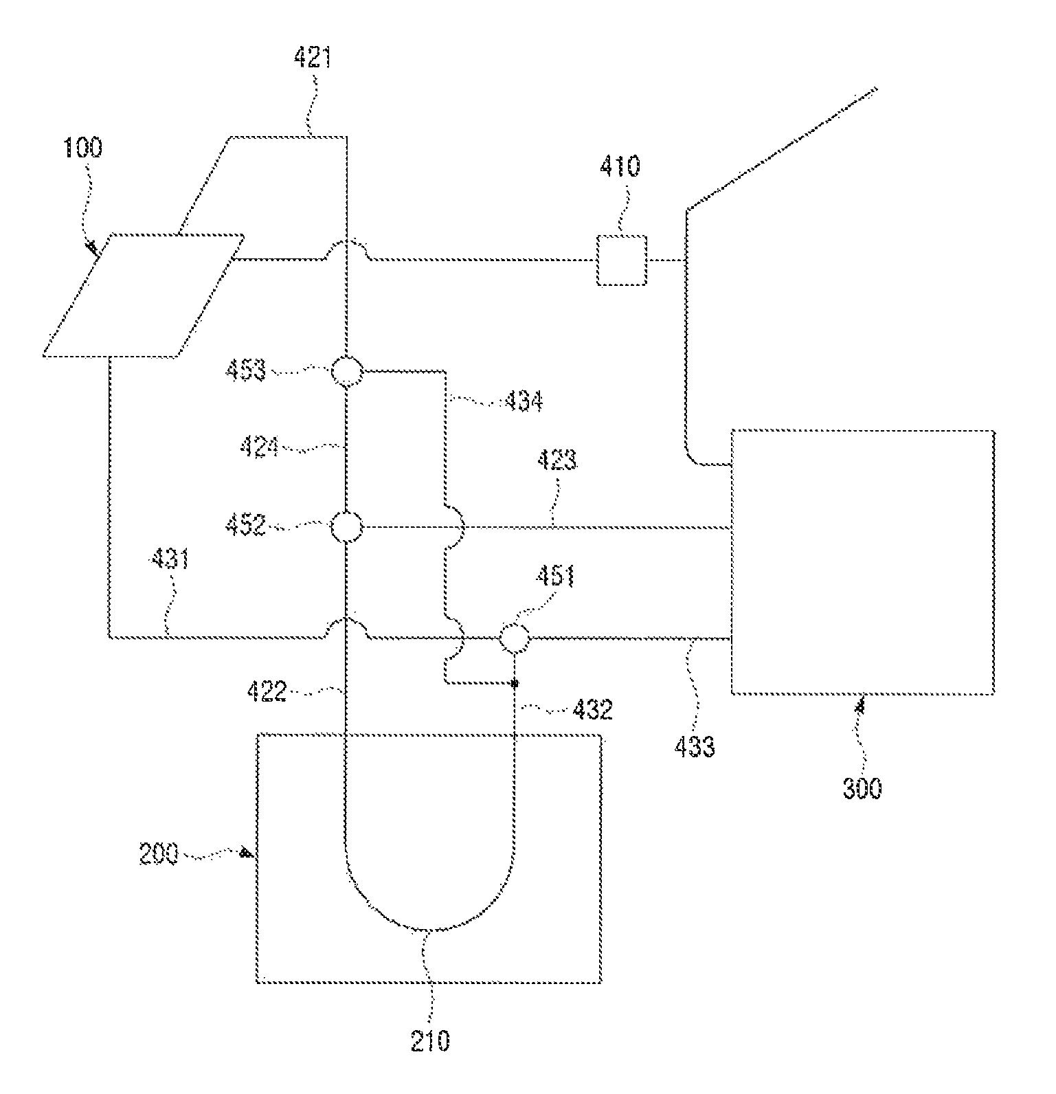
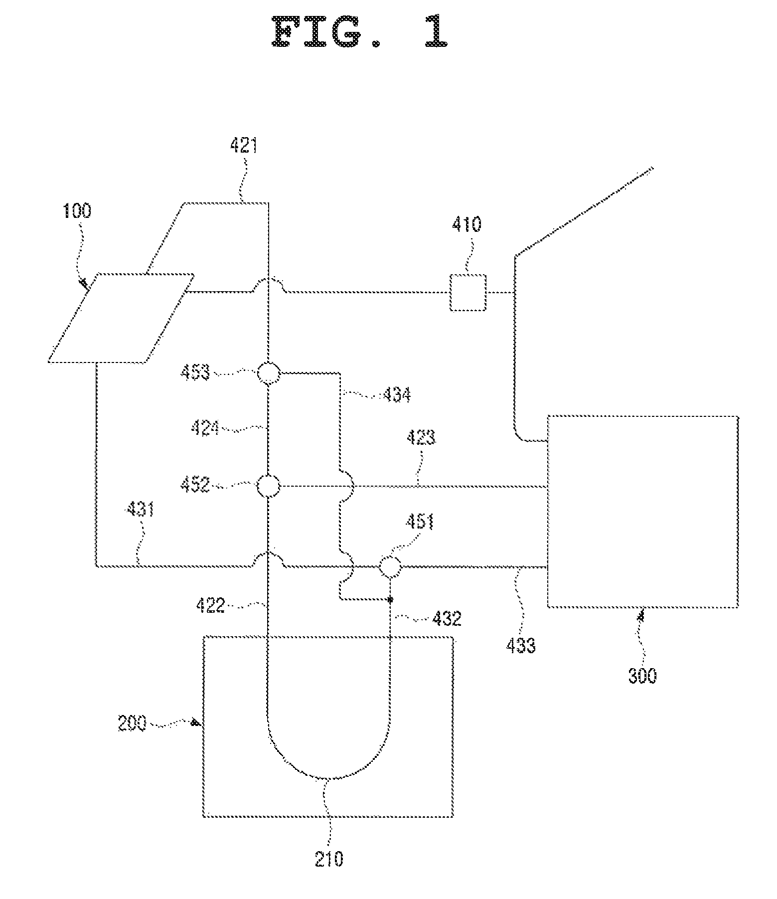
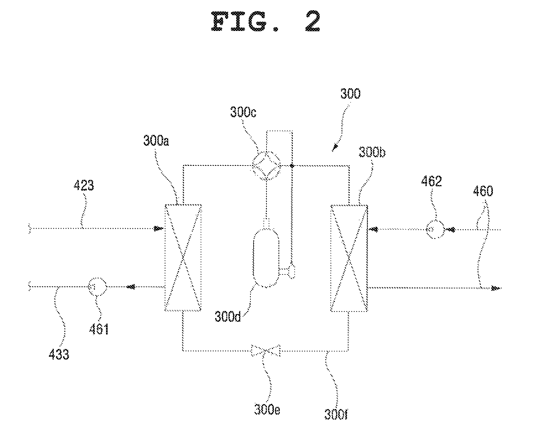
[0059]FIG. 1 illustrates a configuration of a heat-electricity combined production system according to an embodiment of the present invention, and FIG. 2 illustrates a configuration of a heat pump illustrated in the heat-electricity combined production system illustrated in FIG. 1.

[0060]The heat-electricity combined production system illustrated in FIG. 1 includes a solar cell module 100 that produces heat by solar heat and produces electricity by solar light, a geothermal heat exchanger 200 that absorbs geothermal heat, a heat pump 300 that transfers heat produced by the solar cell module 100 and heat absorbed by the geothermal heat exchanger 200 to a load side, and a plurality of pipes 421, 422, 423, 424, 432, 432, 433, and 434 which connect the solar cell module 100, the geothermal heat e...


PUM


Abstract

A heat-electricity combined production system includes: a solar cell module in which a flow path through which a heat source side heating medium heated by solar heat flows, is formed and which generates electricity by solar light; a geothermal heat exchanger that absorbs geothermal heat through the heat source side heating medium; a heat pump including a heat source side heat exchanger that performs heat-exchange between the heat source side heating medium and a refrigerant and a load side heat exchanger that performs heat-exchange between the refrigerant and a load side heating medium; a controller that control the heat source side heating medium to pass through both the solar cell module and the geothermal heat exchanger; and a plurality of pipes that connect the solar cell module, the geothermal heat exchanger and the heat pump.

Description

CROSS-REFERENCE TO RELATED APPLICATION[0001]This application claims priority to and the benefit of Korean Patent Application No. 10-2012-123683, filed on Nov. 2, 2012, the disclosure of which is incorporated herein by reference in its entirety.BACKGROUND[0002]1. Field of the Invention[0003]The present invention relates to a heat-electricity combined production system that utilizes solar energy and geothermal heat, and more particularly, to a heat-electricity combined production system that is capable of producing heat and electricity in a combined manner by fusing solar energy and geothermal heat.[0004]2. Discussion of Related Art[0005]Solar energy has characteristics of an energy resource that is close to non-pollution, no noise and infinity and thus is main alternative energy. In particular, the usage of solar energy is increasing due to regulations and a tendency of controlling the usage of a fossil fuel.[0006]As part of the usage of solar energy, there is a solar cell that is ma...

Claims


Application Information

Patent Timeline
Patent Type & Authority Patents(United States)
IPC IPC(8): F03G7/00B60K16/00F01K13/00F25B30/06F03G7/04F03G6/00F25B27/00
CPCF03G7/04F03G6/00F25B27/002F25B30/06Y02E10/10Y02E10/40Y02E10/46Y02P80/15F03G6/092F03G6/0055F03G4/037F03G4/045F03G4/001
Inventor LEE, EUY-JOONKANG, EUN-CHUL
Owner KOREA INST OF ENERGY RES
Learn More