
Device and method for sewage treatment using variable magnetic field

a magnetic field and sewage treatment technology, applied in biological water/sewage treatment, sustainable biological treatment, separation processes, etc., can solve the problems of low biological treatment efficiency, further affecting the efficiency of sewage treatment, and conventional methods for food industry wastewater treatment cannot meet the requirements, etc., to achieve low reaction efficiency, discharging disqualified effluent, and inability to run smoothly

Active Publication Date: 2016-02-09
NANJING UNIV
View PDF6 Cites 0 Cited by
  • Summary
  • Abstract
  • Description
  • Claims
  • Application Information

AI Technical Summary

Benefits of technology

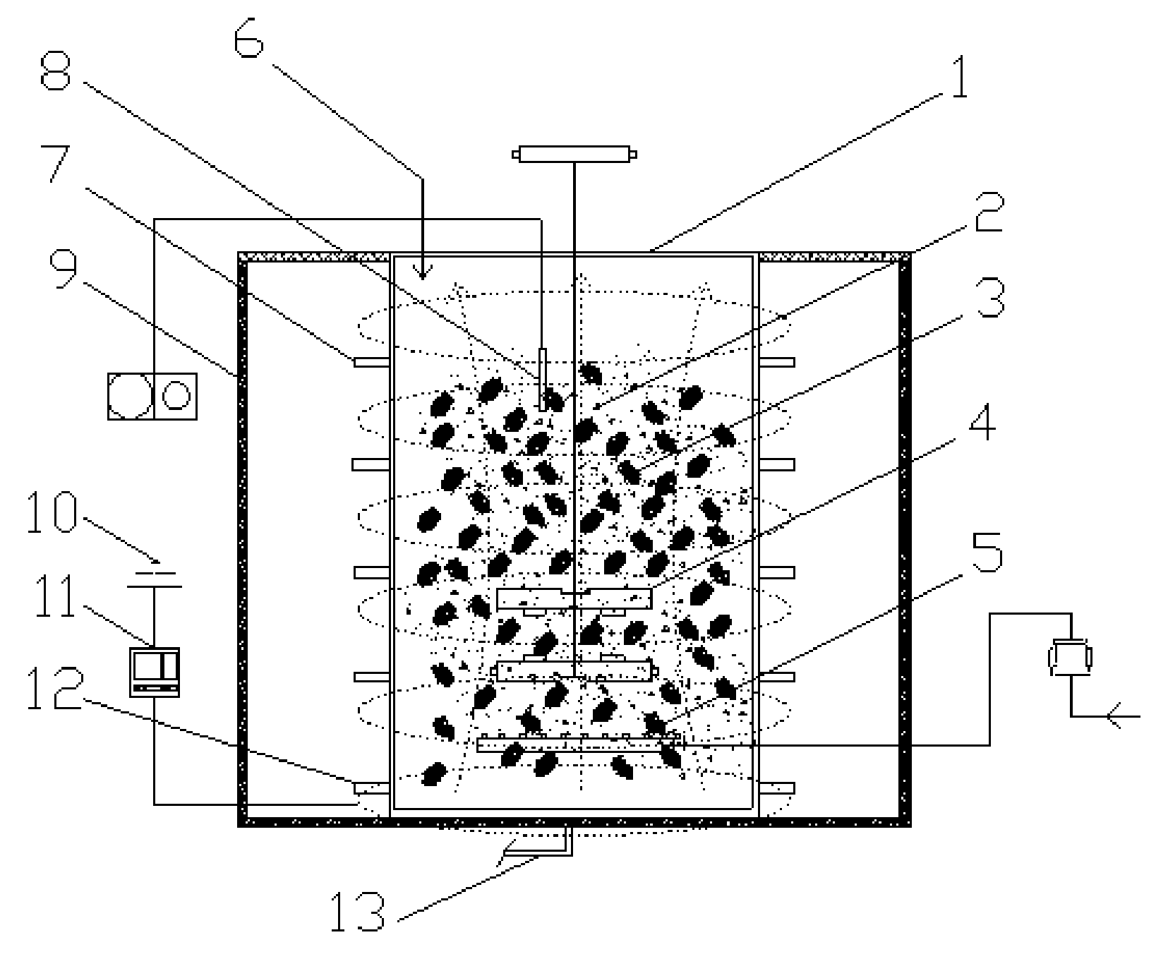
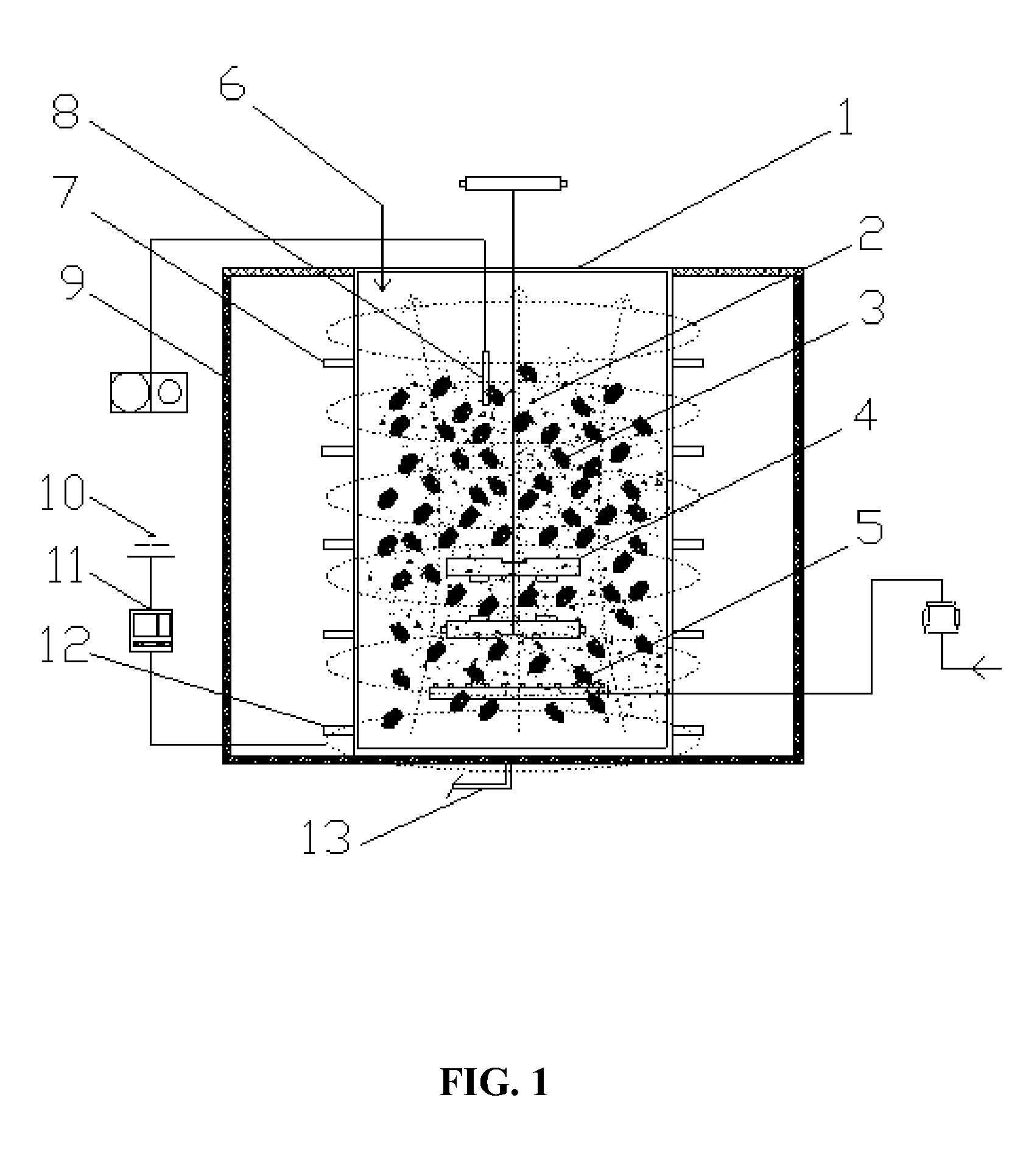
The patent describes a device and method for sewage treatment using a variable magnetic field. The device includes a reactor filled with magnetic powder and activated sludge, and a spiral coil with a current circle evenly around the outer surface of the reactor to form a magnetic field-magnetic powder-microorganism strengthening system. This system improves microorganism activity and degrades organic matters in wastewater. The method involves acclimating the activated sludge in the presence of a magnetic field and then treating grille-filtered food industry wastewater after the reactor runs stably. The treatment process improves the reactor sludge load and organic load, shortens wastewater retention time, and reduces running cost.

Problems solved by technology

However, temperature has an influence on the growth, reproduction, metabolism, species distribution and population size of microorganisms, which further affects the sewage treatment efficiency.
With the increasing strictness of sewage treatment standards, conventional methods for food industry wastewater treatment cannot meet the requirements.
Thus, the biological treatment of wastewater runs at a low efficiency.
However, combining low temperature and magnetic field to treat food industry wastewater has not yet been reported.

Method used


Image

  • Device and method for sewage treatment using variable magnetic field
  • Device and method for sewage treatment using variable magnetic field
  • Device and method for sewage treatment using variable magnetic field

Examples


example 1

[0030]As shown in FIG. 1, a sewage treatment device built in a sewage treatment plant comprises a magnetic powder intensified activated sludge (MPIAS) reactor 1. The MPIAS reactor comprises a stirrer 4, an aeration device 5, magnetic powder 2, activated sludge 3, a water inlet 6, a water outlet 7, and a sludge outlet 13. The water inlet 6 is disposed at the upper end of the reactor 1, the water outlet 7 is disposed on the side wall and the sludge outlet 13 is disposed at the lower end. The reactor 1 is provided with the stirrer 4 and the aeration device 5. The reactor 1 is filled with magnetic powder 2 and activated sludge 3. The magnetic powder 2 is prepared by selecting natural magnetite Fe3O4 as a magnetic seed, finely grinding the magnetic seed to have a particle size of 8-10 microns, and purifying to have a purity of 99.5% using a weak magnetic separator.

[0031]The periphery of the reactor 1 is provided with a magnetic field generator. The magnetic field generator comprises a ma...

example 2

[0038]The wastewater treatment device is the same as that in example 1 except that the thickness of the iron cover 9 is 8 mm.

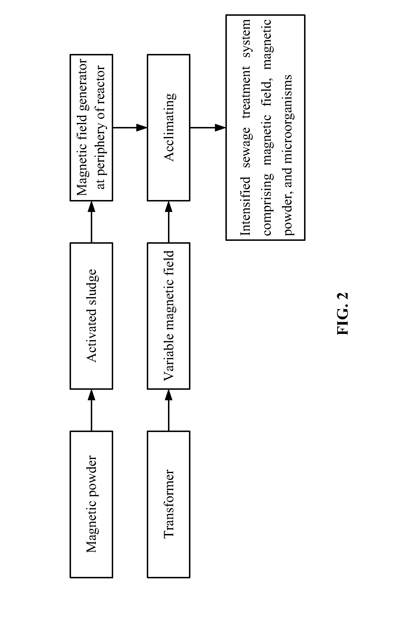
[0039]As shown in FIG. 2, based on the above device for sewage treatment, a method for sewage treatment is described as follows:[0040]a) disposing the magnetic field generator at the periphery of the reactor 1 and placing the reactor 1 into the spiral coil 12 of the magnetic field generator, and allowing the power supply 10 to be an off-state;[0041]b) placing the activated sludge 3 having a concentration of 5000 mg / L and the magnetic powder 2 in the reactor 1 at 15° C., the addition amount of the magnetic powder 2 being 1.2 g / L, introducing simulated food industry wastewater having an organic load of 0.05 kg / (m3·d) into the reactor, and aerating and stirring (300 rpm) the reactor to yield a flocculent mixture of the activated sludge 3 and the magnetic powder 2;[0042]c) culturing the flocculent mixture of the activated sludge 3 and the magnetic powder 2 for 20 ...

example 3

[0045]The wastewater treatment device is the same as that in example 1 except that the thickness of the iron cover 9 is 7 mm.

[0046]As shown in FIG. 2, based on the above device for sewage treatment, a method for sewage treatment is described as follows:[0047]a) disposing the magnetic field generator at the periphery of the reactor 1 and placing the reactor 1 into the spiral coil 12 of the magnetic field generator, and allowing the power supply 10 to be an off-state;[0048]b) placing the activated sludge 3 having a concentration of 4500 mg / L and the magnetic powder 2 in the reactor 1 at a temperature of 10° C., the addition amount of the magnetic powder 2 being 1.0 g / L, introducing simulated food industry wastewater having an organic load of 0.05 kg / (m3·d) into the reactor, and aerating and stirring (250 rpm) the reactor to yield a flocculent mixture of the activated sludge 3 and the magnetic powder 2;[0049]c) culturing the flocculent mixture of the activated sludge 3 and the magnetic...


PUM

PropertyMeasurementUnit
temperatureaaaaaaaaaa
particle sizeaaaaaaaaaa

Abstract

A device for sewage treatment including a reactor and a magnetic field generator. The reactor includes a water inlet at the upper end, a water outlet on the side wall, and a sludge outlet at the lower end. A stirrer and an aeration device are disposed in the reactor. The reactor is filled with magnetic powder and activated sludge. The magnetic field generator includes a magnetic field tester, an iron cover, a power supply, a transformer, and a spiral coil. The spiral coil loops around the outer surface of the reactor. The transformer, the spiral coil, and the power supply are connected in sequence. The iron cover surrounds the periphery and the bottom of the reactor, and the magnetic field tester is disposed within the reactor. A method for sewage treatment using the device is also provided.

Description

CROSS-REFERENCE TO RELATED APPLICATIONS[0001]Pursuant to 35 U.S.C. §119 and the Paris Convention Treaty, this application claims the benefit of Chinese Patent Application No. 201210475408.5 filed Nov. 22, 2012, the contents of which, are incorporated herein by reference. Inquiries from the public to applicants or assignees concerning this document or the related applications should be directed to: Matthias Scholl P. C., Attn.: Dr. Matthias Scholl Esq., 14781 Memorial Drive, Suite 1319, Houston, Tex. 77079.BACKGROUND OF THE INVENTION[0002]1. Field of the Invention[0003]The invention relates to the field of industrial wastewater purification, and more particularly to a device and a method for sewage treatment using variable magnetic field. The device and method are especially suitable in low temperature conditions for strengthening the biological treatment of the food industry wastewater.[0004]2. Description of the Related Art[0005]Biological treatment of food industry wastewater is t...

Claims


Application Information

Patent Timeline
Patent Type & Authority Patents(United States)
IPC IPC(8): C02F1/48B01D59/48C02F3/08C02F3/00C02F3/10
CPCC02F3/085C02F1/485C02F3/107C02F2003/001C02F2305/12Y02W10/15Y02W10/10
Inventor REN, HONGQIANGNIU, CHUANGENG, JINJUXU, KE
Owner NANJING UNIV
Learn More