

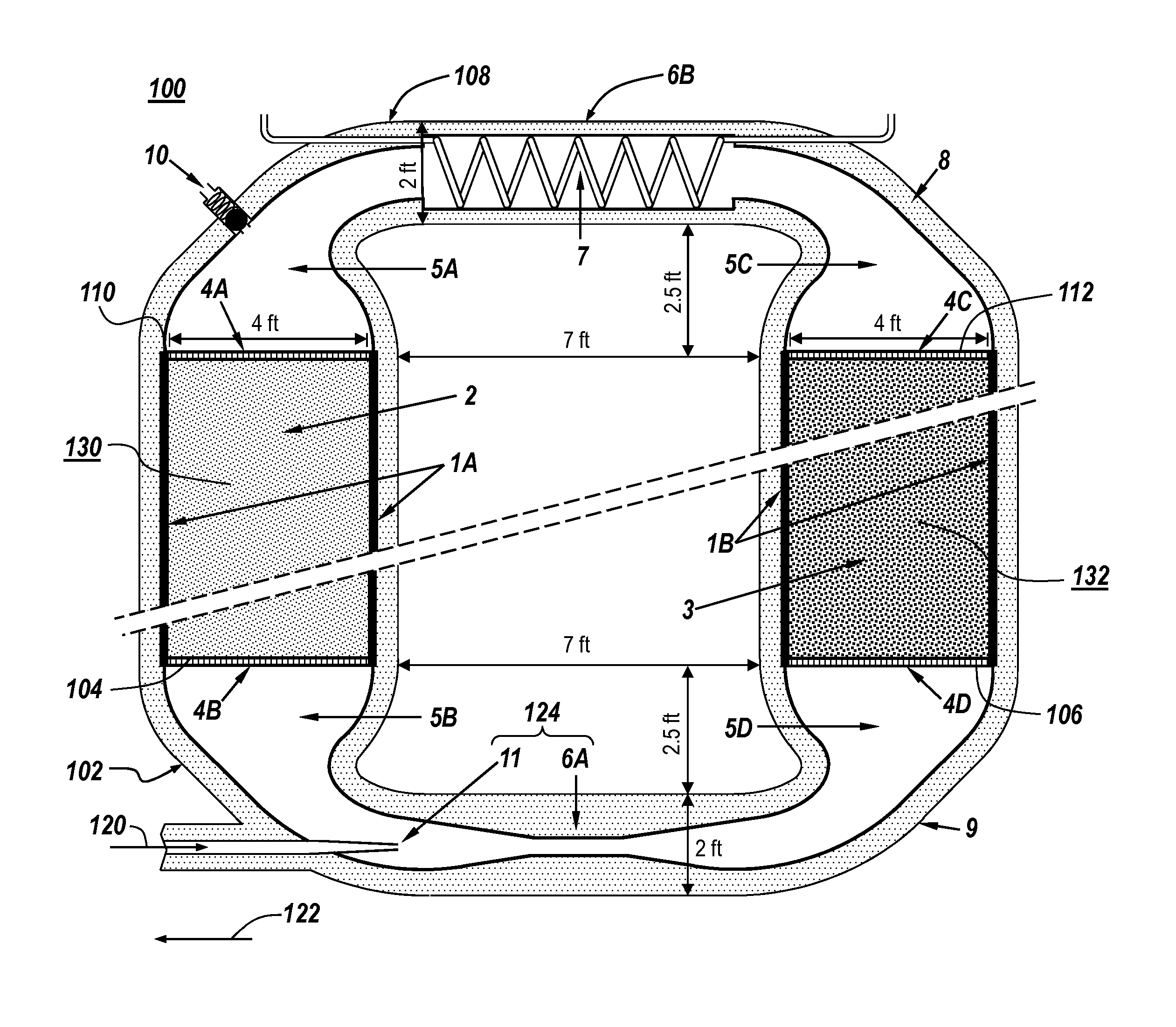
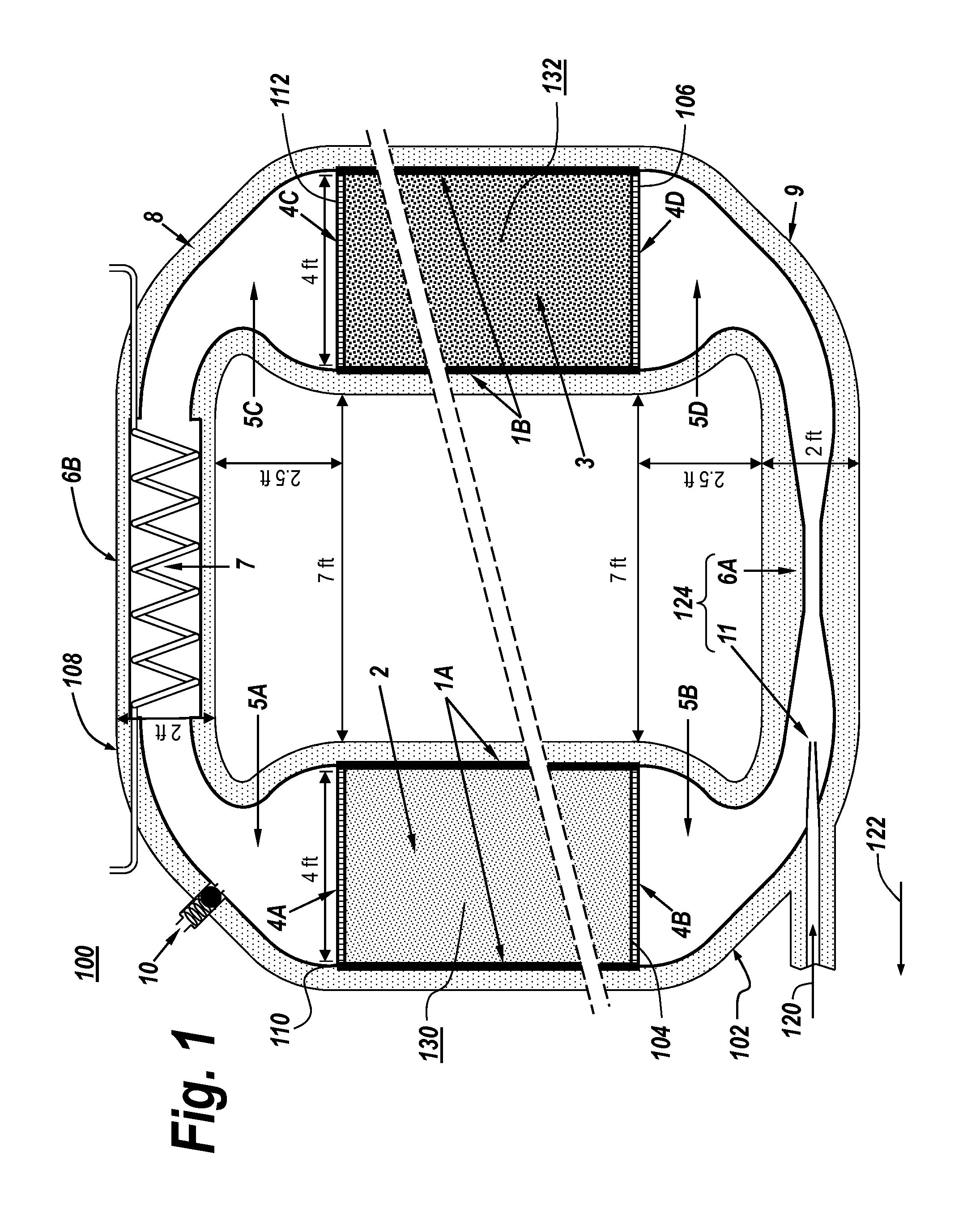
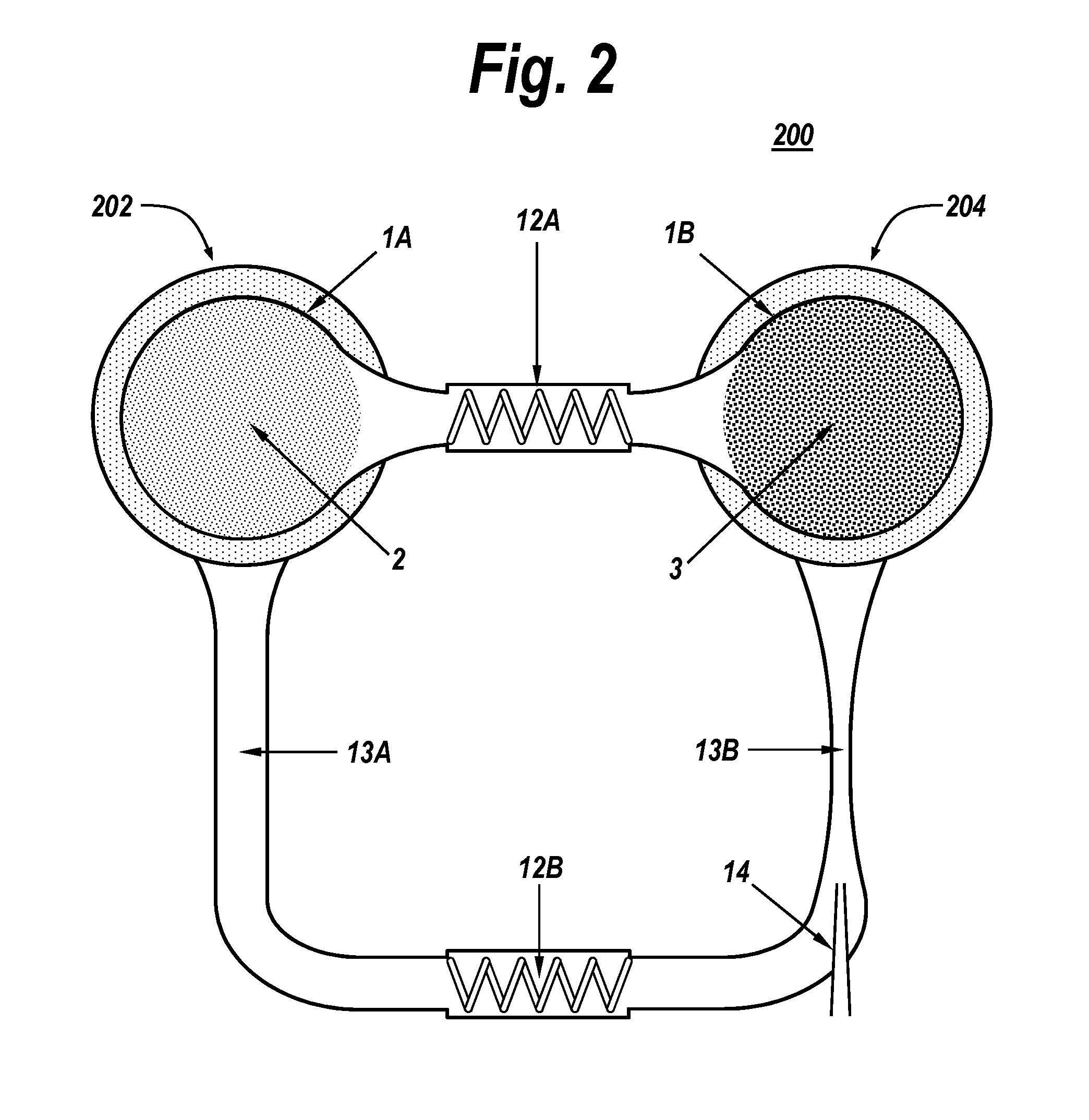
Modular adsorption-enhanced compressed air energy storage system with regenerative thermal energy recycling
a technology of compressed air and energy storage system, applied in the direction of indirect heat exchangers, machines/engines, light and heating apparatus, etc., can solve the problem that the underground components should last many decades without maintenance, and achieve the effect of reducing land area, reducing cost, and effective deploymen
- Summary
- Abstract
- Description
- Claims
- Application Information
AI Technical Summary
Benefits of technology
Problems solved by technology
Method used
Image

Examples
Embodiment Construction
[0022]In the field of adsorption refrigeration and heat pumps, several approaches have been proposed which seek an improved coefficient of performance by causing a “thermal wave” or front to propagate through a packed or fused bed of a particulate adsorbent. Early examples of this approach, which achieved this effect by passing a heat transfer fluid such as a mineral oil through an embedded heat exchanger, may be found in “Solid Adsorbent Heat Pump System”, U.S. Pat. No. 4,610,148 by S. V Shelton (1986), and “Heat Pump Energized by Low-Grade Heat Source”, U.S. Pat. No. 4,637,218 by D. I. Tchernev (1987).
[0023]R. E. Critoph subsequently proposed using the adsorbate vapor itself as the heat transfer fluid, instead of a separate fluid passing through a heat exchanger in the adsorbent bed, thereby producing a “convective thermal wave”. A similar process may also occur in a regenerative heat exchanger, and accordingly, Critoph's student R. Thorpe proposed to use a second packed or fused ...
PUM
 Abstract
Description
Claims
Application Information