Optical device for beam shaping

a beam shaping and optical device technology, applied in the field of optical devices, can solve the problems of devices being able to generate wave front deformation, devices cannot be used to continuously adjust the beam parameter product, and cannot be modified the beam parameter produ

Active Publication Date: 2016-02-16
II VI DELAWARE INC
View PDF11 Cites 7 Cited by
  • Summary
  • Abstract
  • Description
  • Claims
  • Application Information

AI Technical Summary

Benefits of technology

[0012]A device consisting of at least two plate-like optical elements, which have a position dependent thickness and which are positioned in a row at short distance in the optical path of a position limited ray beam, is provided to solve the problem. The two plate-like elements are positioned along an axis transverse to the diffusion direction of the ray beam, and they are displaceable. A position of the plate-like elements called neutral position is defined at the position where the thickness profiles of both elements are inverse to each other. The total sum of the thickness profiles of both optical elements describes a profile, which corresponds to an isosceles triangle, considering a centre, cross section along the displacement axis. It is possible to adjust the inclination of the laterals of the triangular profile considering a centre cross section of the sum of both optical elements by displacing the two optical elements against each other.
[0026]The device can be used to modify at least one dimension parameter of the beam spot in the focal plane without having to modify the focal position.

Problems solved by technology

The mentioned devices cannot be used to adjust the beam parameter product continuously, for example by adjusting the diameter of the ring.
However, it is not possible to modify the beam parameter product.
None of the mentioned devices is able to generate a wave front deformation by means of which the beam parameter product of the laser beam can continuously be adjusted and magnified beginning with its original value.

Method used


Image

  • Optical device for beam shaping
  • Optical device for beam shaping
  • Optical device for beam shaping

Examples


Embodiment Construction

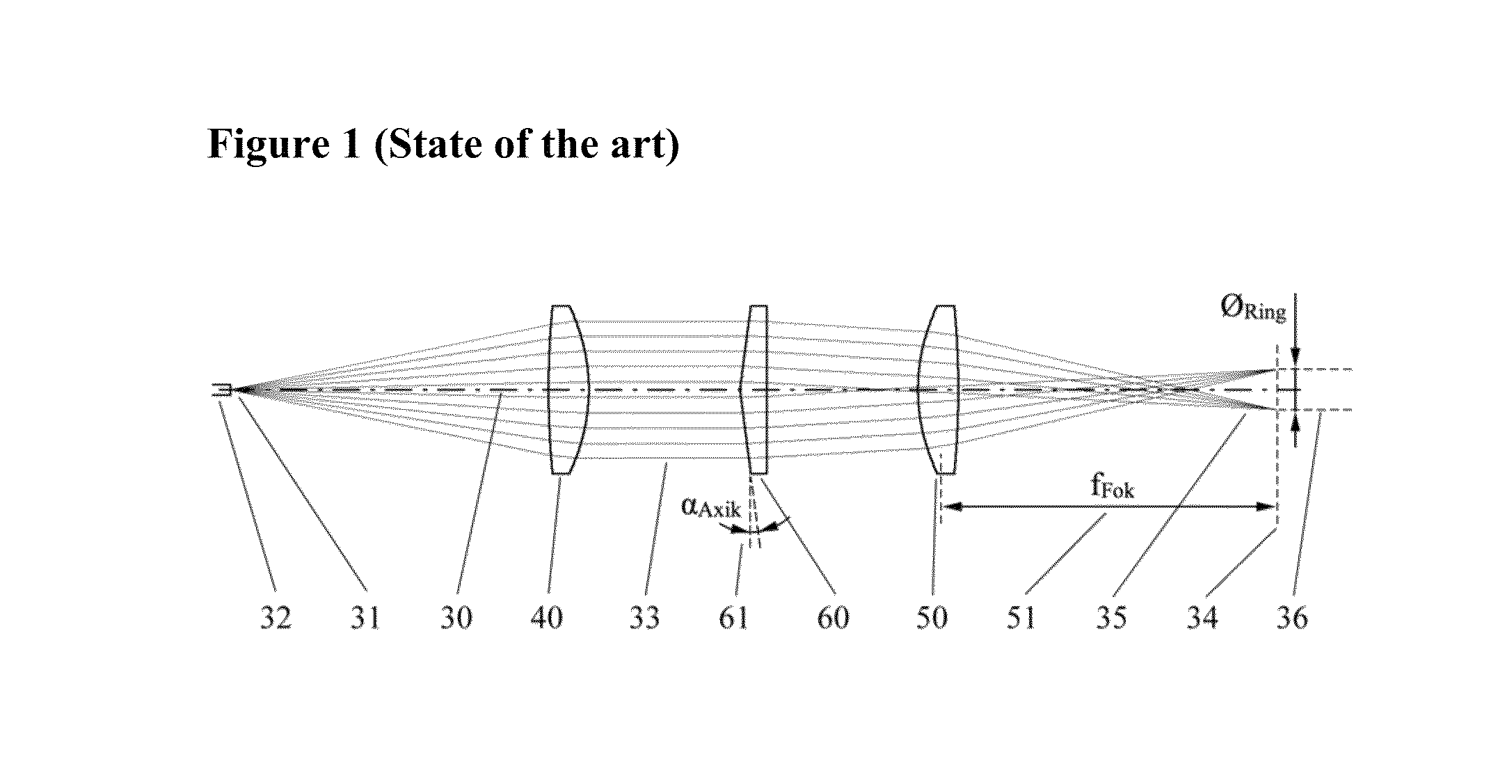
[0041]FIG. 1 shows how a ring-shaped beam focus 35 is generated in the focal plane 34 of laser optics by means of a cone lens or an axicon 60 in laser optics. Typically, laser optics consist of a collimator 40 and a focusing lens 50, which are conjointly positioned on an optical axis 30. A collimator 40 collimates the beam emitted by a beam source 31; a fibre tip 32 can generate the beam source 31, for example. The focusing lens 50 with the focal length 51 images the collimated beam 33 in the focal plane 34. In this context, the axicon 60 can be positioned between the collimator 40 and the focussing lens 50 of laser optics. Such a device is sufficiently mentioned in the state of the art. The cone angle 61 of the axicon has to be modified to adjust the diameter of the ring 36 of the ring-shaped beam spot 35. Modifications are only possible if the axicon 60 is replaced.

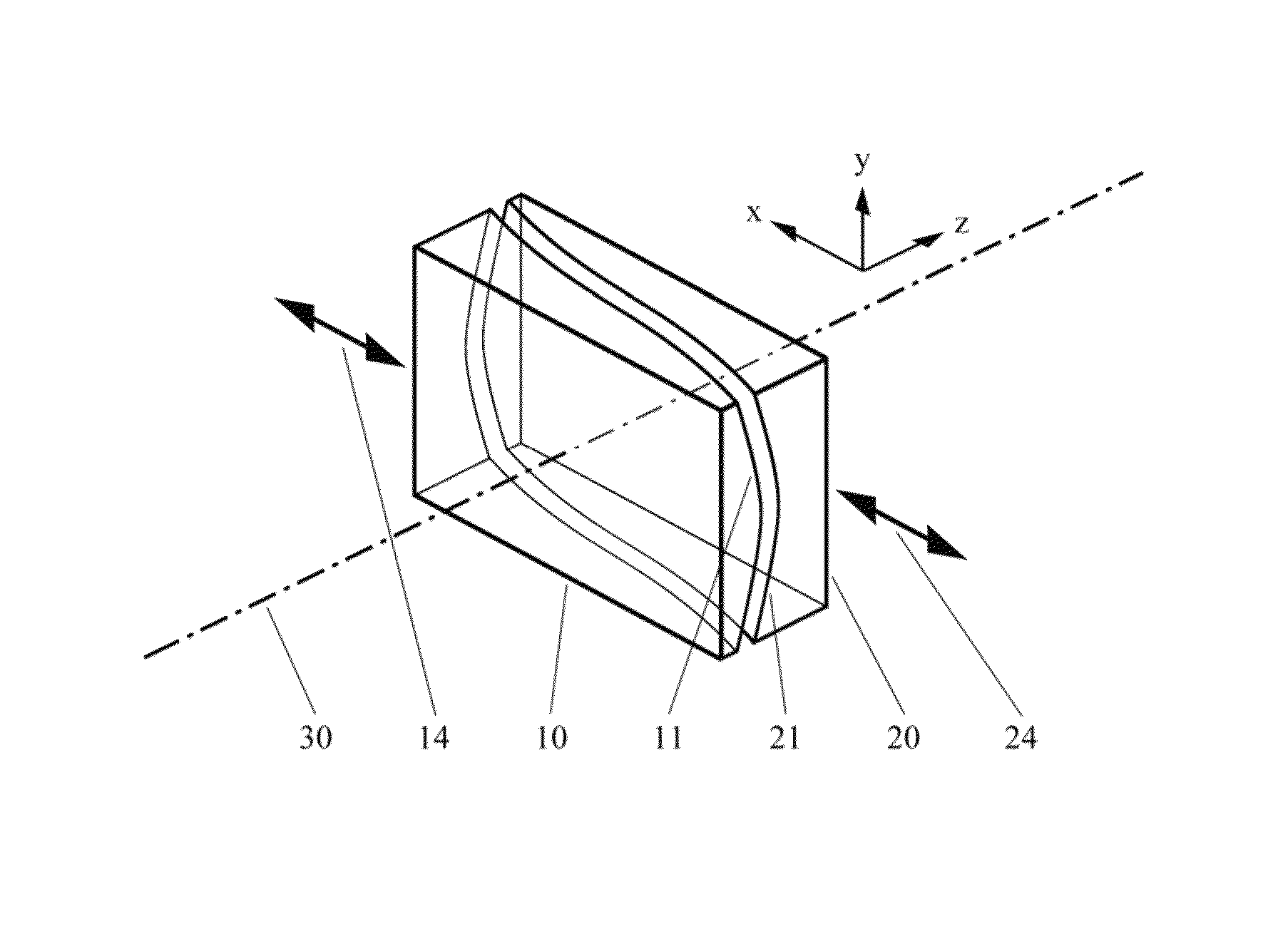
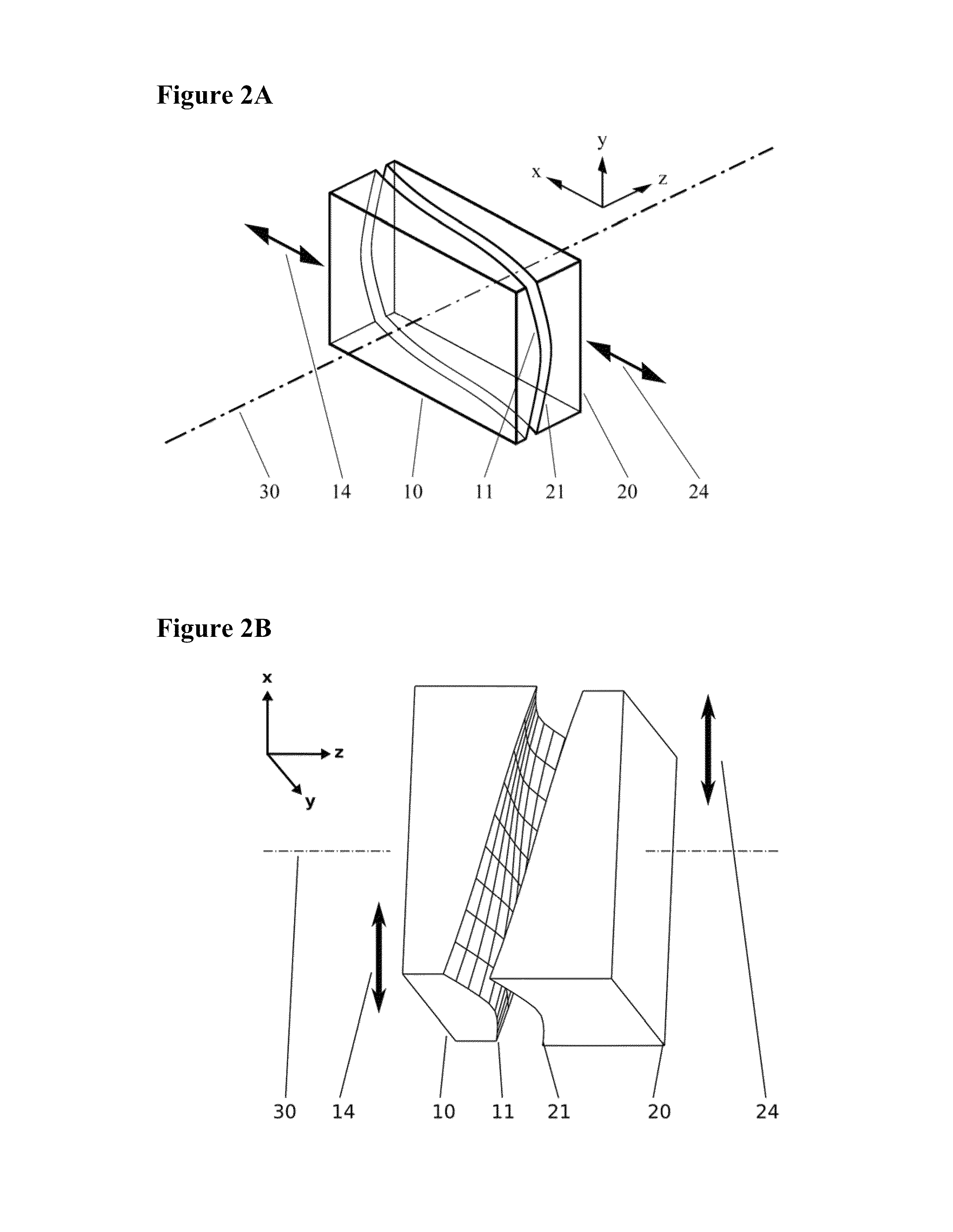
[0042]FIG. 2A shows a schematic representation of the invention. It consists of a first plate-like element 10 and a s...


PUM

PropertyMeasurementUnit
thicknessaaaaaaaaaa
thicknessesaaaaaaaaaa
cone angleaaaaaaaaaa

Abstract

The invention concerns an optical device and its application to generate an adjustable wave front deformation of a laser beam and thus to generate an adjustable beam spot geometry in the focal plane of laser optics. For this purpose, a device is provided which allows adjusting and modifying a laser beam in such a way that a beam spot, the shape of which can be adjusted continuously based on the original focal shape, is generated after focusing the beam, i.e. at least one dimension parameter of the shape of the beam spot has to be variable and adjustable so that the beam parameter product of the beam can also be modified without having to modify the focal position.

Description

BACKGROUND OF THE INVENTION[0001]1. Field of the Invention[0002]The invention concerns an optical device and its application to generate an adjustable wave front deformation of a laser beam. Using such a device aims at modifications of beam spot geometry in the focal range of the laser beam and with it modifications of the beam parameter product of the laser beam.[0003]2. Brief Description of the Related Art[0004]Using laser beaming, for example for material processing, it is often desirable to have the option to use a special beam spot geometry to optimize the work results. A laser beam focus or a beam spot with ring-shaped intensity distribution is required for many applications.[0005]The use of a so-called axicon, for example, is mentioned in the State of the art, that i.e. a lens with a cone-shaped effective surface which is inserted into the optical path of laser processing optics. This type of devices is described in documents DE 28 21 883, DE 100 44 522, DE 102 54 847 or DE 1...

Claims


Application Information

Patent Timeline
Patent Type & Authority Patents(United States)
IPC IPC(8): G02B27/09B23K26/20B23K26/06G02B3/02B23K26/38G02B3/00B23K1/005B23K26/073
CPCG02B27/095B23K1/0056B23K26/0652B23K26/073G02B27/0927G02B27/0955B23K26/0734B23K26/20B23K26/38G02B27/09G02B2003/0093B23K26/382B23K26/21
Inventor CHAN, DANNY
Owner II VI DELAWARE INC
Why Eureka
Try Eureka