Turbine airfoil

a turbine and airframe technology, applied in the field of turbine airframes, can solve the problems of high loss, high erosion, and the effect of only achieving the beneficial effect of efficiency, and achieve the effect of high efficiency of turbomachinery blading and thick wall region

Inactive Publication Date: 2016-02-23
SIEMENS AG
View PDF21 Cites 7 Cited by
  • Summary
  • Abstract
  • Description
  • Claims
  • Application Information

AI Technical Summary

Benefits of technology

[0013]The present invention allows to produce very thin trailing edges without thermal barrier coating systems applied thereon and at the same time minimizing or even avoiding a step at the boundary between the coated surface region and the uncoated surface region. This step is minimized or avoided by providing the mentioned step in the surface of the airfoil body. By choosing the height of the step such that it matches the thickness of the thermal barrier coating system to be applied to form the coated surface region the surface of the applied coating in the coated region can be made to match the surface of the uncoated surface region. This allows to produce a finished surface of the partly coated airfoil which matches the designed definition in the coated surface region as well as in the uncoated surface region. Moreover, since there is no thermal barrier coating at the trailing edge an adverse effect on the airfoil lifetime due to high levels of erosion of the thermal barrier coating at the trailing edge does not occur.
[0015]Furthermore, the inventive turbine airfoil is preferably hollow and comprises at least one cooling opening, in particular realised by a cutback design, at the trailing edge. In this way, the trailing edge can be made particularly thin, if the hollow airfoil body comprises a wall the thickness of which is less in the uncoated surface region than in the coated surface region. The thickness of the wall region can, in particular, decrease over a small transition region on one or both sides of the boundary line. This avoids having a step at the inner surface of the airfoil body at or close to the location of the step in the outer surface.
[0016]An inventive turbine blade, which in particular is a gas turbine vane or blade, comprises an inventive turbine airfoil. The use of an inventive airfoil allows for producing highly efficient turbomachinery bladings.

Problems solved by technology

However, although such superalloys have considerably high corrosion and oxidation resistance, the high temperatures of the combustion gases in gas turbines require measures to improve corrosion and / or oxidation resistance further.
In particular, thick trailing edges result in higher losses.
However, the beneficial effect on the efficiency can only be achieved if the thickness of the trailing edge is rather small.
In addition, as the flow velocity of the gas is the greatest at the trailing edge of the airfoil a thermal barrier coating applied to the trailing edge is prone to high levels of erosion.
However, in U.S. Pat. No. 6,077,036 the pressure side of the airfoil is completely uncoated which means that areas which would not suffer from a higher combined thickness of the cast airfoil body and the coating applied thereon remain unprotected against the temperature the hot combustion gas.
However, like in WO 98 / 10174 the trailing edge is fully coated so that the beneficial effect on blading efficiency can not be achieved.
In US 2009 / 0104356 A1 the method of masking the trailing edge will produce a step in the coating which adversely affects the aerodynamics of the blade.

Method used


Image

  • Turbine airfoil
  • Turbine airfoil

Examples


Embodiment Construction

[0021]An inventive turbine airfoil may be part of a turbine blade or a turbine vane. Turbine blades are fixed to a rotor of the turbine and rotate together with the rotor. They are adapted for receiving momentum from the flowing combustion gas produced by a combustion system. The turbine vanes are fixed to the turbine casing and form nozzles for guiding on the combustion gases so as to optimize the momentum transfer to the rotor blades. The inventive turbine airfoil can, in general, be used in turbine blades as well as in turbine vanes.

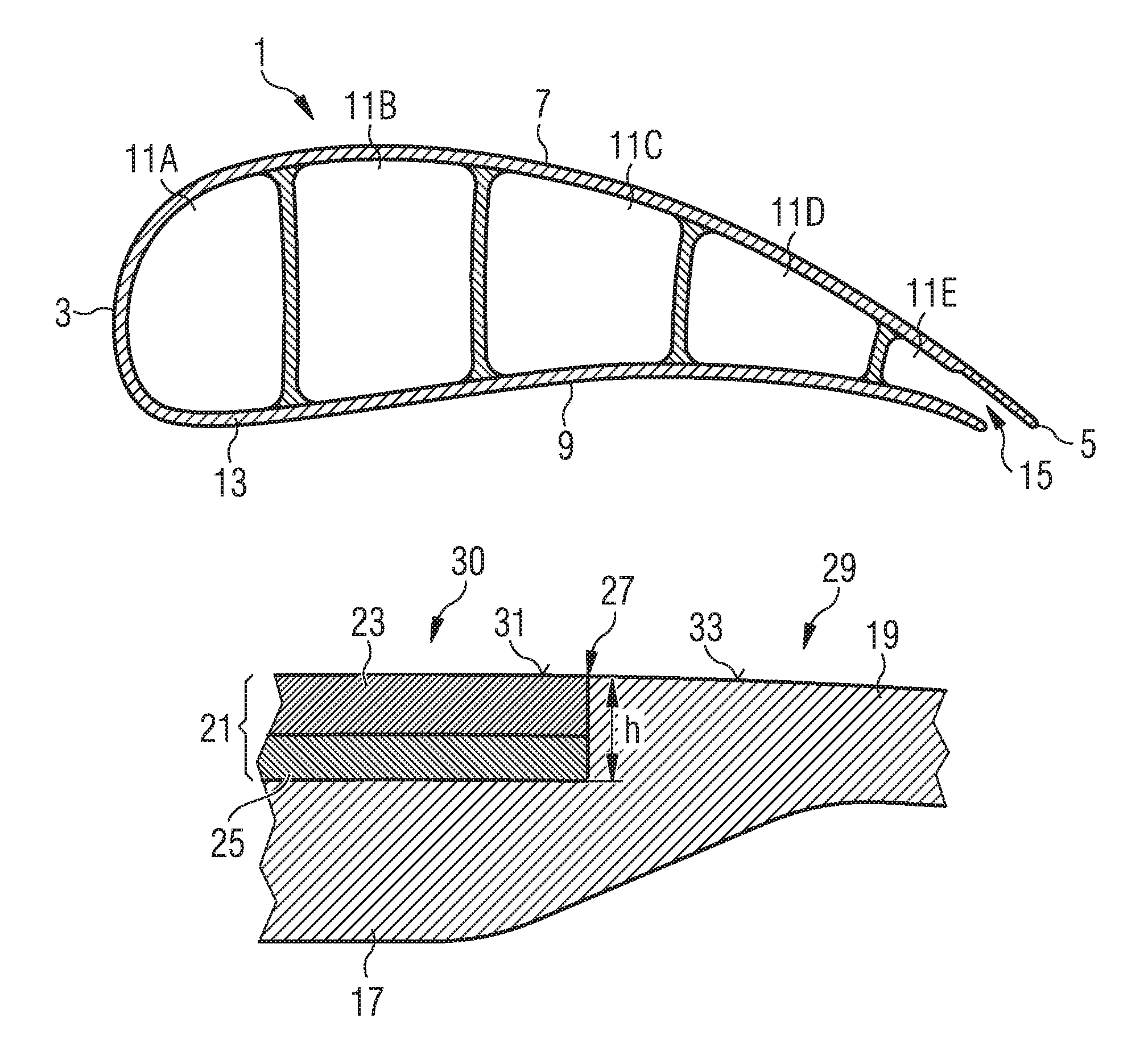
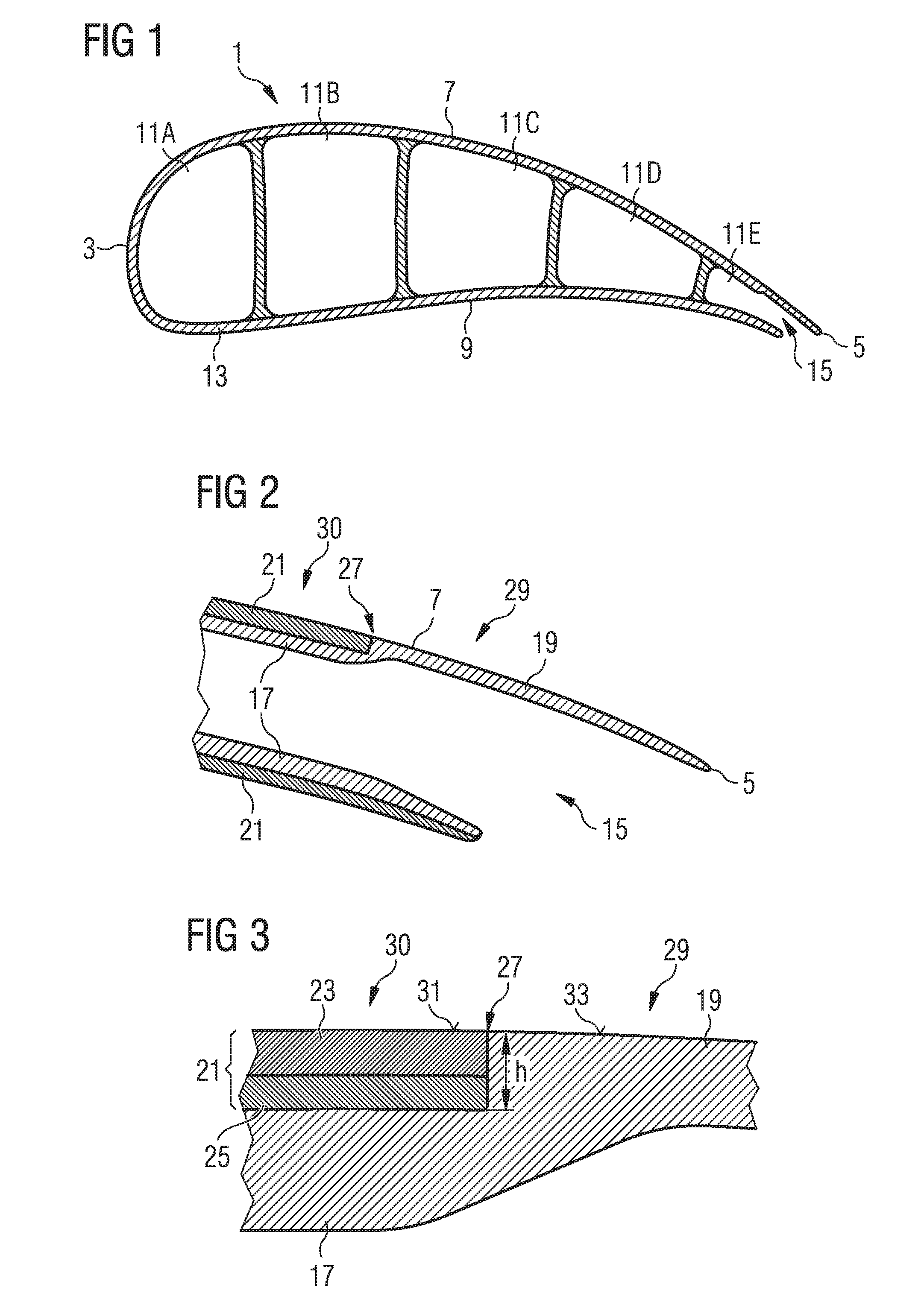
[0022]An inventive airfoil 1 is shown in FIG. 1. It comprises a cast airfoil body 13, a leading edge 3 at which the flowing combustion gases arrive at the airfoil 1—the leading edge 3 being the upstream edge—and a trailing edge 5 at which the combustion gases leave the airfoil 1—the trailing edge 5 being the downstream edge. The exterior surface of the airfoil 1 is formed by a convex suction side 7 and a less convex, and typically concave, pressure si...


PUM


Abstract

A turbine airfoil includes an airfoil body with a leading edge, trailing edge, and an exterior surface including a suction side and a pressure side located opposite to the suction side. The exterior surface shows away from the interior of the airfoil body. A thermal barrier coating system is present on the exterior surface of the airfoil body in a coated surface region. The airfoil also includes an uncoated surface region where a thermal barrier coating system is not present. The uncoated region extends on the suction side of the exterior surface from the trailing edge towards the leading edge to a boundary line between the coated surface region and the uncoated surface region, wherein the boundary line is located on the suction side between the leading edge and the trailing edge. The airfoil body also includes a step in the exterior surface extending along the boundary line.

Description

CROSS REFERENCE TO RELATED APPLICATIONS[0001]This application is the US National Stage of International Application No. PCT / EP2011 / 052169, filed Feb. 15, 2011 and claims the benefit thereof. The International Application claims the benefits of European application No. 10154125.8 EP filed Feb. 19, 2010. All of the applications are incorporated by reference herein in their entirety.FIELD OF INVENTION[0002]The present invention relates to a turbine airfoil which can be used in a gas turbine vane or blade.BACKGROUND OF INVENTION[0003]The airfoils of gas turbines are typically made of nickel or cobalt based superalloys which show high resistance against the hot and corrosive combustion gases present in gas turbine. However, although such superalloys have considerably high corrosion and oxidation resistance, the high temperatures of the combustion gases in gas turbines require measures to improve corrosion and / or oxidation resistance further. Therefore, airfoils of gas turbine blades and ...

Claims


Application Information

Patent Timeline
Patent Type & Authority Patents(United States)
IPC IPC(8): F01D5/28F01D5/18
CPCF01D5/288F01D5/286F01D5/186F05D2230/90F05D2250/713F05D2260/95
Inventor BATT, STEPHENMUGGLESTONE, JONATHANWONG, LI SHING
Owner SIEMENS AG
Why Eureka
Try Eureka