Reflector arrangement for attachment to a wireless communications terminal

a wireless communication terminal and reflector technology, applied in the direction of antenna support/mounting, antenna details, electrical equipment, etc., can solve the problems of affecting the transmission of signals, affecting the reception of signals, and requiring more gain, and achieve good impedance matching to the patch antenna. , the effect of cheap production

Active Publication Date: 2016-02-23
CAMBIUM NETWORKS
View PDF14 Cites 171 Cited by
  • Summary
  • Abstract
  • Description
  • Claims
  • Application Information

AI Technical Summary

Benefits of technology

[0013]The configuration of the reflector arrangement for use with a patch antenna as a feed antenna for the sub-reflector may provide a compact design that is cheap to produce and that may provide a good impedance match to the patch antenna.

Problems solved by technology

However, in some deployment scenarios, for example when the customer premises are far away from the base station, there may be a requirement for more gain than the internal antenna is designed to provide.
However, such arrangements are typically bulky and require the orientation of a terminal that has already been installed to be changed.
However, this arrangement may not present a good impedance match to the transmitter in the terminal, so that signals may be reflected back into the power amplifier, potentially causing distortion of transmitted signals.
Furthermore, the arrangement may be bulky and expensive to manufacture.
However, this typically requires the use of large amounts of potentially expensive material, and may add significantly to the weight of the terminal.

Method used


Image

  • Reflector arrangement for attachment to a wireless communications terminal
  • Reflector arrangement for attachment to a wireless communications terminal
  • Reflector arrangement for attachment to a wireless communications terminal

Examples


Embodiment Construction

[0025]By way of example, embodiments of the invention will now be described in the context of a broadband fixed wireless access radio communications system operating in accordance with an IEEE 802.11a, b, g, n or ac standard. However, it will be understood that this is by way of example only and that other embodiments may involve other wireless systems, and may apply to point-to-point and point-to-multipoint systems, and to systems operating according to cellular radio standards.

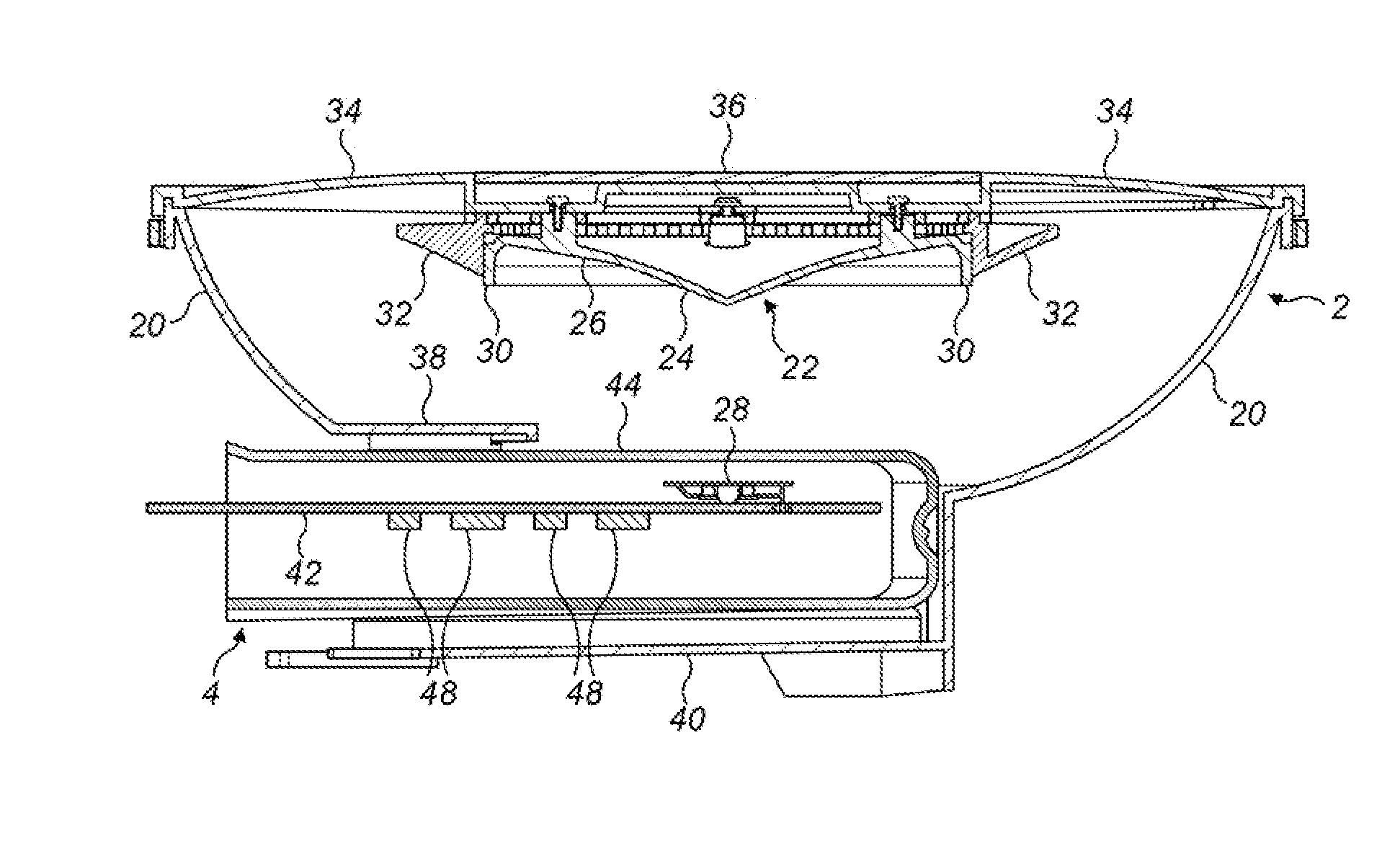
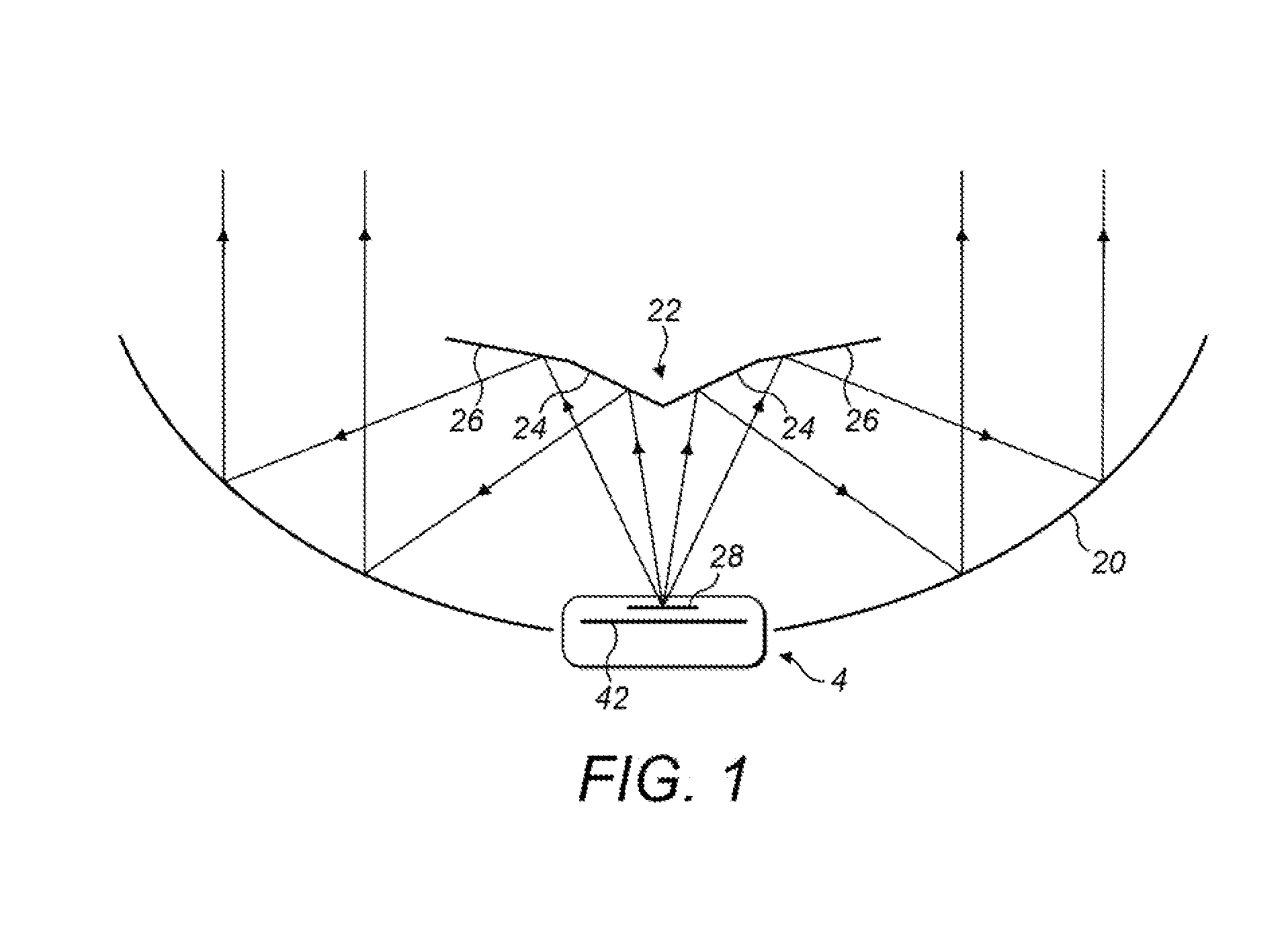
[0026]FIG. 1 shows an embodiment of the invention, in which a reflector arrangement 20, 22 is configured so that it may be attached to a wireless communications terminal 4 as shown. The reflector arrangement has a main reflector 20, and the internal antenna in the terminal, typically a patch antenna, acts as a feed antenna for a sub-reflector 22, which collects radiation from the patch antenna 28, 42 and reflects radiation towards the main reflector 20. The main reflector is shaped to produce a radiated beam...


PUM


Abstract

A reflector arrangement is configured for attachment to a wireless communications terminal having a patch antenna. The patch antenna includes a patch radiator in a substantially parallel relationship with a ground plane, and the patch antenna produces a radiation beam of a predetermined beamwidth. The reflector arrangement is configured, when attached to the terminal, to produce a radiation beam of reduced beamwidth relative to the predetermined beamwidth. The reflector arrangement comprises a main reflector and a sub-reflector for reflecting radiation towards the main reflector, and the reflector arrangement is configured such that, when attached to the terminal, the patch antenna acts as a feed antenna for the sub-reflector. The sub-reflector is arranged to collect the radiation from the patch antenna and to reflect the beam towards the main reflector such that the main reflector produces the radiated beam of reduced beamwidth.

Description

BACKGROUND OF THE INVENTION[0001]The present invention relates generally to radio frequency antenna arrangements, and more specifically, but not exclusively, to a reflector arrangement for attachment to a wireless communications terminal to increase antenna gain for transmission and reception of microwave frequency radiation in a wireless communications system.[0002]Modern wireless communications systems place great demands on the antennas used to transmit and receive signals. In particular in a fixed wireless access system, in which a wireless terminal known as customer premises equipment may be installed at a determined orientation for communication with a base station, it may be required that an antenna produces a radiation pattern that has well defined directional characteristics so as to reduce path loss to the base station and to minimise interference to neighbouring systems, but there is also a requirement that the antenna be small, and cheap to produce.[0003]Typically, a wir...

Claims


Application Information

Patent Timeline
Patent Type & Authority Patents(United States)
IPC IPC(8): H01Q15/14H01Q1/24H01Q19/12H01Q19/10H01Q19/19
CPCH01Q1/243H01Q19/19
Inventor LEY, JOHN, F.
Owner CAMBIUM NETWORKS
Why Eureka
Try Eureka