Method for resistance braze repair

a technology of resistance braze and repair method, which is applied in the direction of manufacturing tools, transportation and packaging, and so on, can solve the problems of difficult subsequent structural welding, difficult to repair or new fabrication of nickel and cobalt based superalloy materials used to manufacture turbine components, and blades that are susceptible to solidification, so as to achieve the effect of not degrading the structural properties of the component substra

Active Publication Date: 2016-03-01
SIEMENS ENERGY INC
View PDF61 Cites 0 Cited by
  • Summary
  • Abstract
  • Description
  • Claims
  • Application Information

AI Technical Summary

Benefits of technology

[0016]Accordingly, an object of the present invention is to create a method for performing joining of or repairs on surfaces of metallic components, including superalloy components such as turbine vanes and blades, so that subcomponents can be joined or that cracks and other surface defects can be repaired, without degrading structural properties of the component substrate.
[0017]Another object of the present invention is to create a method for performing joining of or repairs on surfaces of metallic components, including superalloy components such as turbine vanes and blades, with proven, repeatable repair techniques and repair equipment that do not require complex welding or post-repair heat treatment procedures that might also degrade structural properties of the component substrate.
[0018]Yet another object of the present invention is to create a method for performing joining of or repairs on surfaces of metallic components, including superalloy components such as turbine vanes and blades, with minimized hand labor and relatively short repair cycle times.

Problems solved by technology

Repair or new fabrication of nickel and cobalt based superalloy material that is used to manufacture turbine components, such as cast turbine blades, is challenging, due to the metallurgic properties of the finished blade material.
The finished turbine blade alloys are typically strengthened during post casting heat treatments, which render them difficult to perform subsequent structural welding.
When a blade constructed of such a material is welded with filler of the same or similar alloy, the blade is susceptible to solidification (aka liquation) cracking within and proximate to the weld, and / or strain age (aka reheat) cracking during subsequent heat treatment processes intended to restore the superalloy original strength and other material properties comparable to a new component.
As noted above high heat application to superalloy materials negatively impacts their structural properties.
Liquefied braze alloy must not contact the resistance electrodes, or else the electrode material becomes contaminated.
If liquefied braze alloy is interposed between an electrode and the substrate material they may become permanently attached, ruining the electrode and possibly damaging the substrate component.
Previously developed superalloy repair methods all have various favorable and less favorable attributes.
The electric resistance brazing and welding methods described and claimed in the commonly owned co-pending patent applications, by removal of damaged material and replacement with a splice of new material, provide for high-quality structural repairs with relatively simple repair apparatus and methods, but may not be considered as commercially cost effective for relatively simple cosmetic surface repairs on superalloy components, such as turbine blades and vanes.
Generally diffusion brazing processes require relatively long thermal cycling times, complicated metal treatment processes with relatively expensive treatment equipment and relative slow through put times for service repair as compared to known torch or electric resistance brazing techniques.
Torch brazing requires significant hand labor that increases costs, slows repair time and introduces the potential for quality control variations dependent upon the skill level of an individual metal worker who is performing the repair.
Other commonly known cosmetic repair electric resistance brazing methods are not suitable for repairing relatively wide or extensive cracks due to potential electrode damage and / or inadvertent substrate attachment caused by liquefied brazing alloy overruns out of the cracks.

Method used


Image

  • Method for resistance braze repair
  • Method for resistance braze repair
  • Method for resistance braze repair

Examples


Embodiment Construction

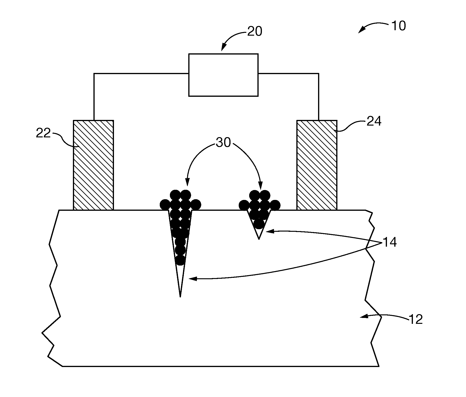
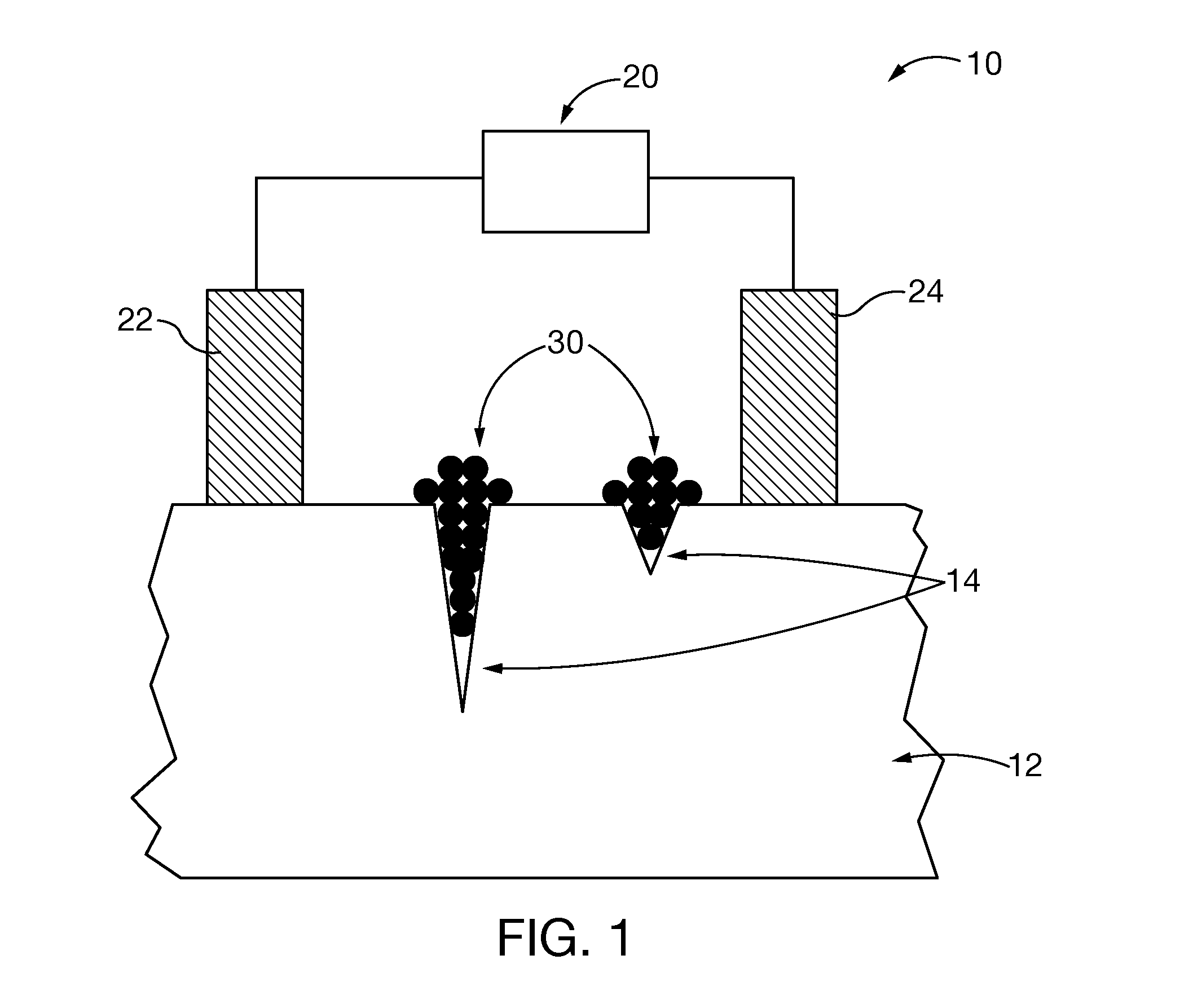
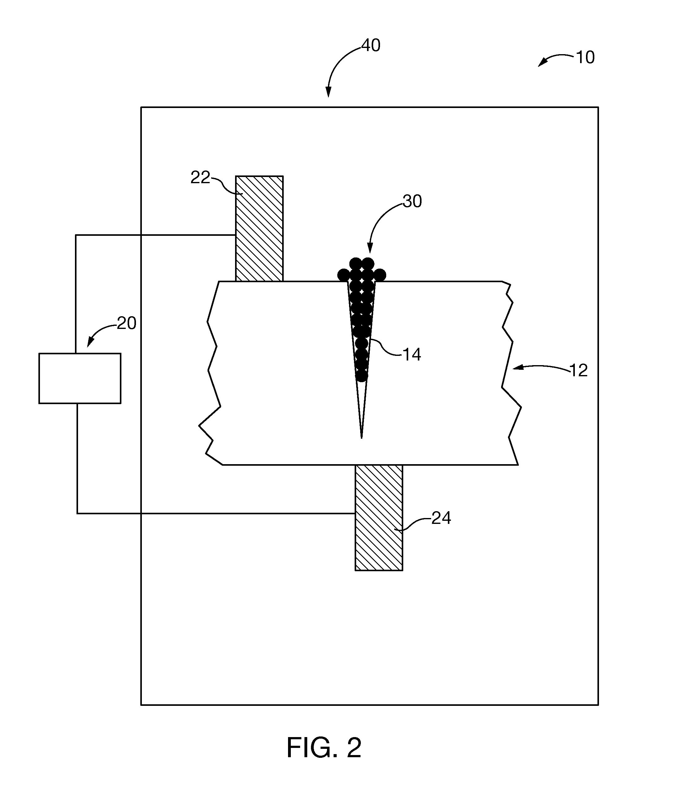
[0031]After considering the following description, those skilled in the art will clearly realize that the teachings of the present invention can be readily utilized in joining and / or repair of metallic substrates, and more particularly repair of superalloy turbine blades and turbine vanes. Brazing alloys having high electrical resistivity are bonded to the substrate by passing electric current generated by a known electric resistance brazing apparatus through the brazing alloy. Heat generated by the flowing electric current is concentrated in the high resistivity brazing alloy rather than in the substrate. The concentrated heat is sufficient to melt the brazing alloy, causing it to bond to the adjoining superalloy substrate material without degrading structural properties of the superalloy.

[0032]FIG. 1 shows apparatus 10 for resistance braze repairing an exemplary substrate 12, such as a superalloy turbine blade, having one or more surface crack defects 14. A current generating appa...


PUM

PropertyMeasurementUnit
metallicaaaaaaaaaa
electrical resistivityaaaaaaaaaa
melting pointaaaaaaaaaa

Abstract

Metallic components, including superalloy components such as turbine vanes and blades, are joined or repaired by electric resistance with a high electrical resistivity brazing alloy composition. In some embodiments the brazing alloy comprises filler metal selected from the group consisting of nickel, iron, and cobalt base alloy and elements selected from the group consisting of phosphorous (P), boron (B), silicon (Si), germanium (Ge), sulfur (S), selenium (Se), carbon (C), tellurium (Te) and manganese (Mn). In performing the method of the present invention a high electrical resistivity brazing alloy composition is introduced within a substrate defect or interposed between two substrates that are to be joined. An electric current is passed through the brazing alloy until the alloy melts and bonds to the adjoining substrate. High resistivity of the brazing alloy concentrates heat generated by the current flow in the brazing alloy rather than in the substrate.

Description

CROSS-REFERENCE TO RELATED APPLICATIONS[0001]This application claims priority to the benefit of and incorporates by reference in their entirety U.S. Provisional Application entitled “Resistance Braze Repair Of Superalloys”, filed Mar. 30, 2012 and assigned Ser. No. 61 / 618,252; as well as co-pending U.S. Utility patent application Ser. No. 13 / 352,475, entitled “Projection Resistance Brazing Of Superalloys”; and Ser. No. 13 / 352,468 entitled “Projection Resistance Welding Of Superalloys” both filed on Jan. 18, 2012.BACKGROUND OF THE DISCLOSURE[0002]1. Field of the Invention[0003]The invention relates to methods for joining or repair of metal components, including advanced superalloy components, by resistance brazing. More particularly, the present invention methods utilize high-resistivity braze fillers that melt with relatively low heat input by application of electric current, without impacting structural properties of the underlying substrate metal. In some embodiments, the inventio...

Claims


Application Information

Patent Timeline
Patent Type & Authority Patents(United States)
IPC IPC(8): B23K1/00B23K1/08B23K1/008
CPCB23K1/0004B23K1/008B23K1/0018Y10T428/12986
Inventor SANSOM, DAVID, GBRUCK, GERALD, J.
Owner SIEMENS ENERGY INC
Why Eureka
Try Eureka