Superalloy laser cladding with surface topology energy transfer compensation

a superalloy and surface topology technology, applied in the direction of glue vessels, machines/engines, nuclear engineering, etc., can solve the problems of difficult subsequent structural welding, difficult to repair nickel and cobalt based superalloy materials used in turbine components, and blades are susceptible to solidification, so as to achieve the effect of not degrading the structural properties of the component substra

Active Publication Date: 2014-03-13
SIEMENS ENERGY INC
View PDF22 Cites 32 Cited by
  • Summary
  • Abstract
  • Description
  • Claims
  • Application Information

AI Technical Summary

Benefits of technology

[0017]Accordingly, an object of the invention is to create a laser welding method for cladding superalloy components, such as turbine vanes and blades that facilities uniform welds with desired localized fusion along a translation path without degrading structural properties of the component substrate.

Problems solved by technology

Repair of nickel and cobalt based superalloy material that is used to manufacture turbine components, such as turbine blades, is challenging, due to the metallurgic properties of the finished blade material.
The finished turbine blade alloys are typically strengthened during post casting heat treatments, which render them difficult to perform subsequent structural welding.
When a blade constructed of such a material is welded with filler metal of the same or similar alloy, the blade is susceptible to solidification (aka liquation) cracking within and proximate to the weld, and / or strain age (aka reheat) cracking during subsequent heat treatment processes intended to restore the superalloy original strength and other material properties comparable to a new component.
Creating arrays of laser-clad deposits often results in microcracks and defects in the deposited material and underlying substrate in the heat affected zone material.
Some defects are related to lack of fusion (LoF) that is common when there is insufficient localized laser optical energy heat input.
This results in over-melting, over-heating and over-stressing of the crack sensitive substrate material 40, which may unnecessarily instigate subsequent hot cracking and / or strain age cracking.

Method used


Image

  • Superalloy laser cladding with surface topology energy transfer compensation
  • Superalloy laser cladding with surface topology energy transfer compensation
  • Superalloy laser cladding with surface topology energy transfer compensation

Examples


Embodiment Construction

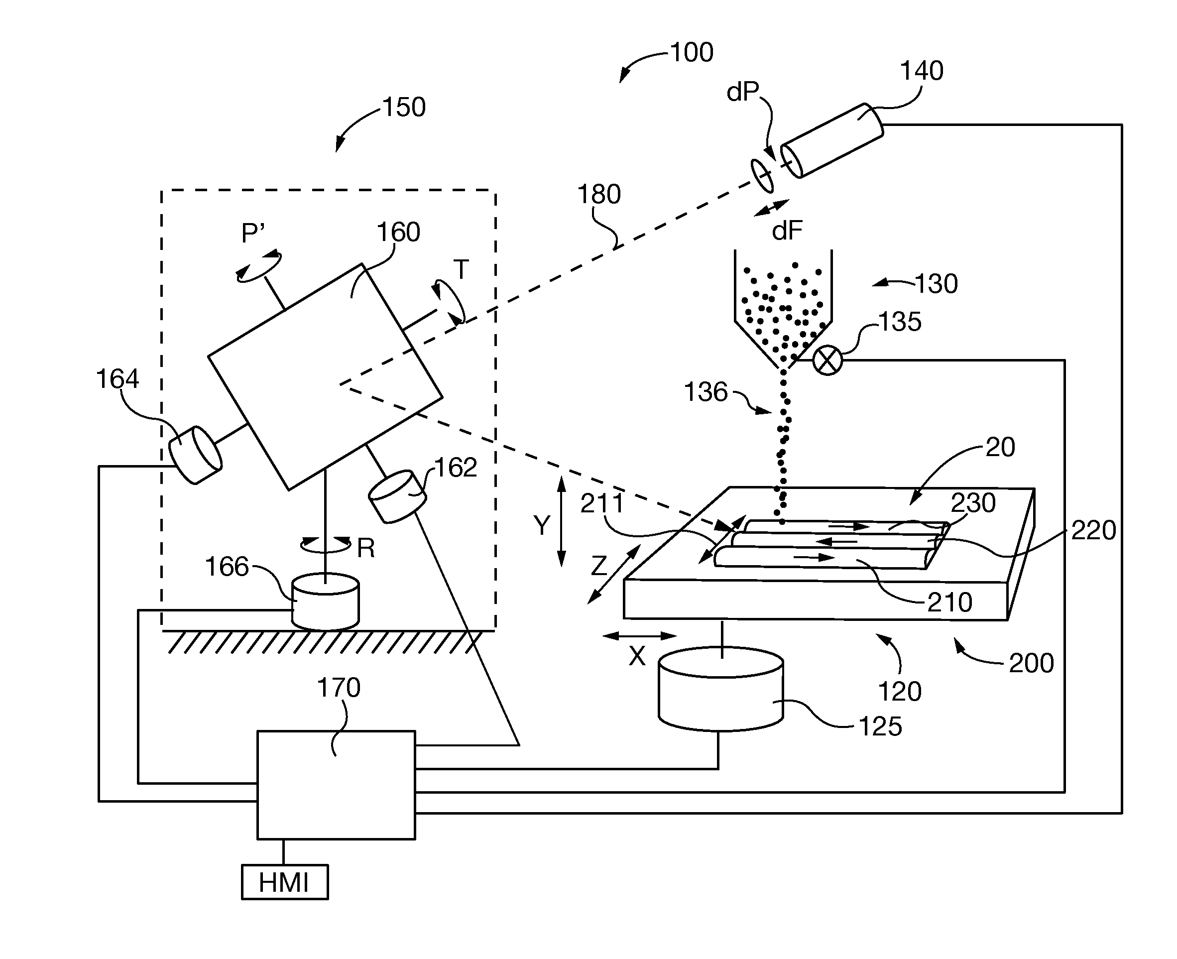
[0035]After considering the following description, those skilled in the art will clearly realize that the teachings of the invention can be readily utilized in repair of superalloy components, such as turbine blades and vanes, by a laser beam welding method that promotes bonding of the superalloy substrate to one or more cladding layers without substrate thermal degradation. The present invention laser cladding methods vary laser optical energy transfer rate to compensate for localized substrate topology variations, so that the energy transfer to the filler and substrate remains uniform during a welding pass.

[0036]Sufficient laser optical energy is transferred to the welding filler material and underlying substrate to assure filler melting and adequate substrate surface wetting for good fusion. However, energy transfer is maintained below a level that jeopardizes substrate thermal degradation. Optical energy transfer to the filler and substrate is maintained uniformly as the laser b...


PUM

PropertyMeasurementUnit
optical energyaaaaaaaaaa
thermal degradationaaaaaaaaaa
energy transferaaaaaaaaaa

Abstract

A superalloy substrate, such as a turbine blade or vane, is fabricated or repaired by laser beam welding to clad one or more layers on the substrate. Laser optical energy is transferred to the welding filler material and underlying substrate to assure filler melting and adequate substrate surface wetting for good fusion. Energy transfer is maintained below a level that jeopardizes substrate thermal degradation. Optical energy transfer to the filler and substrate is maintained uniformly as the laser beam and substrate are moved relative to each other along a translation path by varying the energy transfer rate to compensate for localized substrate topology variations.

Description

CROSS-REFERENCE TO RELATED APPLICATIONS[0001]This application incorporates by reference commonly owned, co-pending United States utility patent application entitled “LASER CLADDING SYSTEM FILLER MATERIAL DISTRIBUTION APPARATUS”, Attorney Docket Number 2012P09234US, filed concurrently herewith and assigned Ser. No. [to be assigned].BACKGROUND OF THE DISCLOSURE[0002]1. Field of the Invention[0003]The invention relates to methods for cladding superalloy components, such as service-degraded turbine blades and vanes, by laser beam welding. More particularly, the present invention methods weld one or more filler material layers to substrates along weld translation paths and regulate laser optical energy to compensate for localized substrate topology variations, facilitating uniform or deliberately modified energy transfer rates along the paths.[0004]2. Description of the Prior Art[0005]“Structural” repair of gas turbine or other superalloy components is commonly recognized as replacing da...

Claims


Application Information

Patent Timeline
Patent Type & Authority Applications(United States)
IPC IPC(8): F04D29/38B05C11/00B32B37/06B05D3/06
CPCB23K26/342B23K2103/26Y10T29/49737Y10T29/49742Y10T29/49746Y10T29/49732Y10T29/49721Y10T29/49718Y10T29/49719Y10T29/49318Y10T29/49316B23K2101/001B23K26/082F05D2230/31F05D2230/80F01D5/005B23K2103/08
Inventor BRUCK, GERALD J.KAMEL, AHMEDSHINN, BRANDON W.
Owner SIEMENS ENERGY INC
Why Eureka
Try Eureka