Method and apparatus for real-time measurement of fuel gas compositions and heating values

a technology which is applied in the field of real-time, in situ measurement of fuel gas composition and heating value, can solve the problems of not being able to detect not being able to achieve the effect of essentially providing real-time information of fuel gas properties, and not being able to achieve the effect of detecting all of these gases using a single inexpensive sensor, etc., to reduce the effect of sensor cross-sensitivity, efficient process control optimization

Active Publication Date: 2016-03-22
NORTH CAROLINA STATE UNIV +1
View PDF13 Cites 7 Cited by
  • Summary
  • Abstract
  • Description
  • Claims
  • Application Information

AI Technical Summary

Benefits of technology

[0010]Accordingly, it is one object of this invention to provide a method and apparatus for determining the composition and heating value of fuel gas mixtures in real-time which overcomes the inaccuracies associated with the cross-sensitivity of known sensors.
[0011]This and other objects of the invention are addressed by an apparatus for real-time, in situ measurement of fuel gas compositions and heating values comprising three independent sensors—a near infrared sensor for measuring concentrations of hydrocarbons and carbon dioxide, a mid infrared sensor for measuring concentrations of carbon monoxide, a semiconductor-based sensor for measuring concentrations of hydrogen, and means for reducing the effects of the cross-sensitivities of these sensors. The apparatus of this invention may be integrated with engines, turbines, or similar combustion equipment for efficient process control and optimization.
[0012]In one particular embodiment, an apparatus for real-time, in situ measurement of gas compositions including concentrations of hydrocarbons, carbon dioxide, carbon monoxide and hydrogen gas in accordance with the invention includes a near infrared sensor for measuring light intensity in a wavelength range of 900 to 1700 nm and providing an absorption spectrum dependent on the concentrations of hydrocarbons and carbon dioxide. The apparatus also includes a mid infrared sensor for measuring light intensity in a range of in a wavelength higher than the near infrared sensor and up to 15 μm and generating an analog output directly proportional to the concentration of carbon monoxide and a semiconductor based sensor for measuring the concentration of hydrogen gas. The apparatus further includes a data processor having a computer program for reducing the effects of cross-sensitivities of the sensors to components other than target components of the sensors.
[0013]The means for reducing the effects of the cross-sensitivities of the sensors is in the form of a hardware control and data acquisition system in which the raw measurements from the sensors are arranged in a first data matrix, the fuel gas composition and heating values are arranged in a second data matrix, and the data matrices are processed using a multivariate technique selected from the group consisting of principal component regression, partial least squares regression, and partial least squares regression 2, producing models that correlate sensor measurements to component compositions and total heating value of the fuel gas.

Problems solved by technology

Further, as combustion is a very fast process, the analysis and measurement of fuel compositions and heating values must necessarily be correspondingly fast as well.
Gas chromatography, however, typically requires at least several minutes to analyze a gas sample and, thus, does not essentially provide real-time information of fuel gas properties.
However, not all of these gases can be detected using a single inexpensive sensor.
Known sensors suitable for use in detecting these gases are, however, problematic due to the fact that such gas sensors are generally cross-sensitive to one or more gases other than the specific target gas of the sensor.
However, not all the components of conventional and alternative fuels, e.g., hydrogen, absorb light in the NIR range.

Method used


Image

  • Method and apparatus for real-time measurement of fuel gas compositions and heating values
  • Method and apparatus for real-time measurement of fuel gas compositions and heating values
  • Method and apparatus for real-time measurement of fuel gas compositions and heating values

Examples


Embodiment Construction

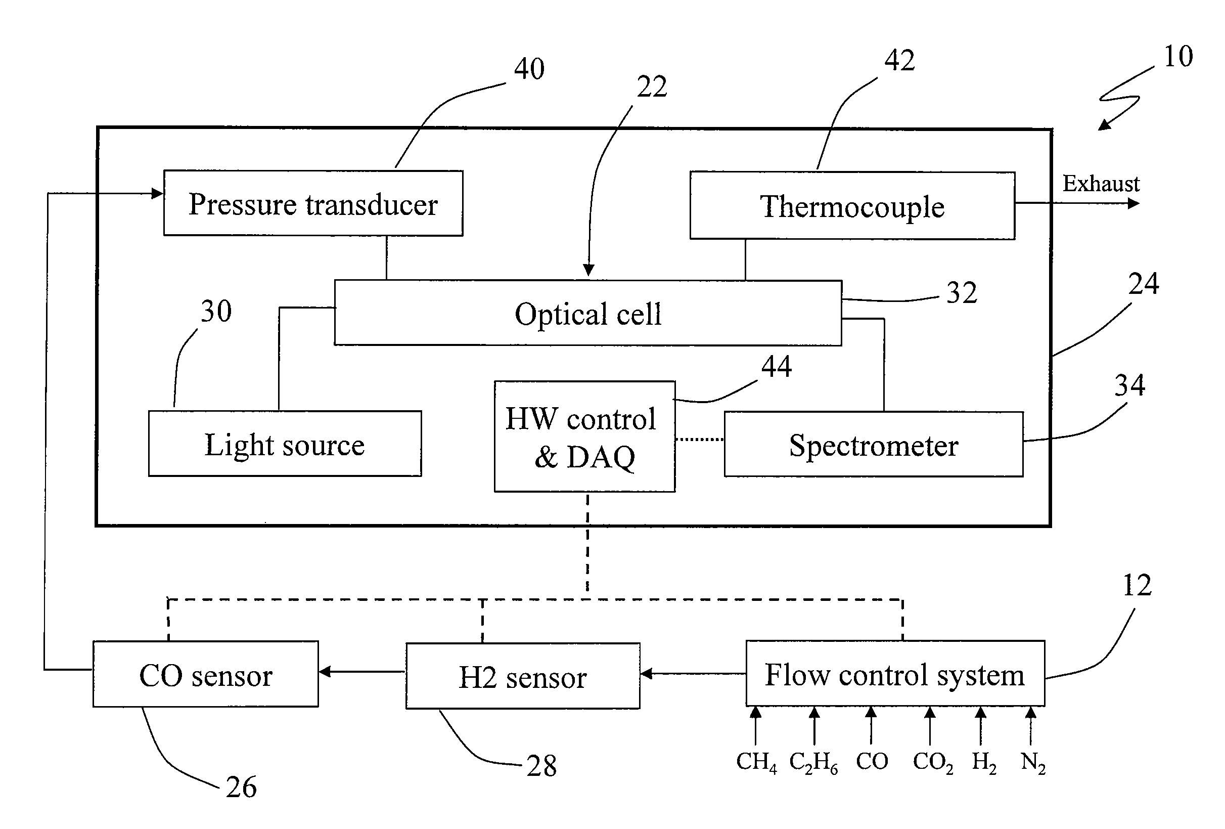
[0022]Turning to FIG. 3, there is illustrated a simplified schematic diagram of a processing system, generally designated by the reference numeral 10, for measuring the fuel gas composition and heating value of a fuel gas in real-time in accordance with one embodiment of this invention.

[0023]The processing system 10 includes a flow control system, generally designated by the reference numeral 12, whereby selected gases such as methane, ethane, carbon monoxide, carbon dioxide, hydrogen and nitrogen, for example, can desirably be introduced for analysis and processing in accordance with the invention.

[0024]The apparatus of this invention advantageously employs both optical and non-optical sensors. Thus, the system 10 includes optical sensors include a near infrared sensor 22, such as part of a gas quality sensor assembly 24 and a mid infrared sensor 26 as well as a non-optical sensor in the form of a semiconductor based sensor 28.

[0025]The near infrared sensor 22 includes a light sour...


PUM

PropertyMeasurementUnit
wavelengthaaaaaaaaaa
wavelengthsaaaaaaaaaa
heating valueaaaaaaaaaa

Abstract

An exemplary embodiment can be an apparatus for real-time, in situ measurement of gas compositions and heating values. The apparatus includes a near infrared sensor for measuring concentrations of hydrocarbons and carbon dioxide, a mid infrared sensor for measuring concentrations of carbon monoxide and a semiconductor based sensor for measuring concentrations of hydrogen gas. A data processor having a computer program for reducing the effects of cross-sensitivities of the sensors to components other than target components of the sensors is also included. Also provided are corresponding or associated methods for real-time, in situ determination of a composition and heating value of a fuel gas.

Description

STATEMENT REGARDING FEDERALLY SPONSORED RESEARCH OR DEVELOPMENT[0001]This invention was made with government support under contract no. DE-EE0000556 awarded by the Department of Energy. The government has certain rights in the invention.BACKGROUND OF THE INVENTION[0002]1. Field of the Invention[0003]This invention generally relates to a method and apparatus for real-time, in situ measurement of fuel gas compositions and heating values. In one aspect, this invention relates to the use of infrared sensors for measuring fuel gas compositions. In one aspect, this invention relates to the use of semiconductor sensors for measuring fuel gas compositions. In one aspect, this invention relates to a method for determining the heating value of fuel gas compositions.[0004]2. Description of Related Art[0005]Globally increasing demand for energy and volatility in supply and pricing of natural gas and fossil fuels along with increasingly more stringent environmental restrictions, such as calls fo...

Claims


Application Information

Patent Timeline
Patent Type & Authority Patents(United States)
IPC IPC(8): G01N33/22G01N21/3504G01N21/85G01N21/359G01N21/05
CPCG01N33/225G01N21/3504G01N21/359G01N21/85G01N21/05G01N2021/8578G01N2201/129
Inventor ZELEPOUGA, SERGUEIPRATAPAS, JOHN M.SAVELIEV, ALEXEI V.JANGALE, VILAS V.
Owner NORTH CAROLINA STATE UNIV
Why Eureka
Try Eureka