Wound treatment device with elastically deformable vacuum producing element

a vacuum producing element and treatment device technology, applied in wound drains, suction drainage containers, bandages, etc., can solve the problem of compressing sponges upon expanding presses against the sensitive wound surface, and achieve the effect of reducing time and the cost of wound treatmen

Active Publication Date: 2016-04-05
BSN MEDICAL GMBH & CO KG
View PDF41 Cites 73 Cited by
  • Summary
  • Abstract
  • Description
  • Claims
  • Application Information

AI Technical Summary

Benefits of technology

[0012]The encased absorption body can be one which is interspersed with superabsorbents. The envelope can have pores whose size does not greatly exceed that of the superabsorbing particles. In this way, the wound secretions sucked up remain inside the envelope until the absorption body is removed from the wound and help improve the climate of the wound space, i.e., maintain the moist surroundings. The wound exudate does not necessarily have to be taken away through an additional conduit, unless there is an excess of wound exudate.
[0014]Finally, the shaped absorbing piece or the pouch with absorber particles contained therein can be placed directly on the wound, without having to use the mentioned encased sheet-like absorption body.
[0015]In order to kill germs, the encased absorption body and / or the additional absorption body of fleece or foam plastic or an anti-adhesive film element which can be placed directly on the wound can be provided with substances containing silver or copper, for example, in nanocrystalline form. As the anti-adhesive film element, one can use a perforated so-called wound spacer grid, which is arranged between the wound surface and the absorption body. Substances containing zinc are also possible, and can support the wound healing process.
[0033]as a dressing to regulate the air humidity, since the absorption body releases the aqueous components back into the air through their vapor pressure;
[0039]thanks to the use of the encased absorption body, the moist environment within the wound cavity can be maintained;
[0043]the time and the costs of the wound treatment can be reduced.

Problems solved by technology

The drawback in both instances is that the compressed sponge upon expanding presses against the sensitive wound surface.

Method used


Image

  • Wound treatment device with elastically deformable vacuum producing element
  • Wound treatment device with elastically deformable vacuum producing element
  • Wound treatment device with elastically deformable vacuum producing element

Examples


Embodiment Construction

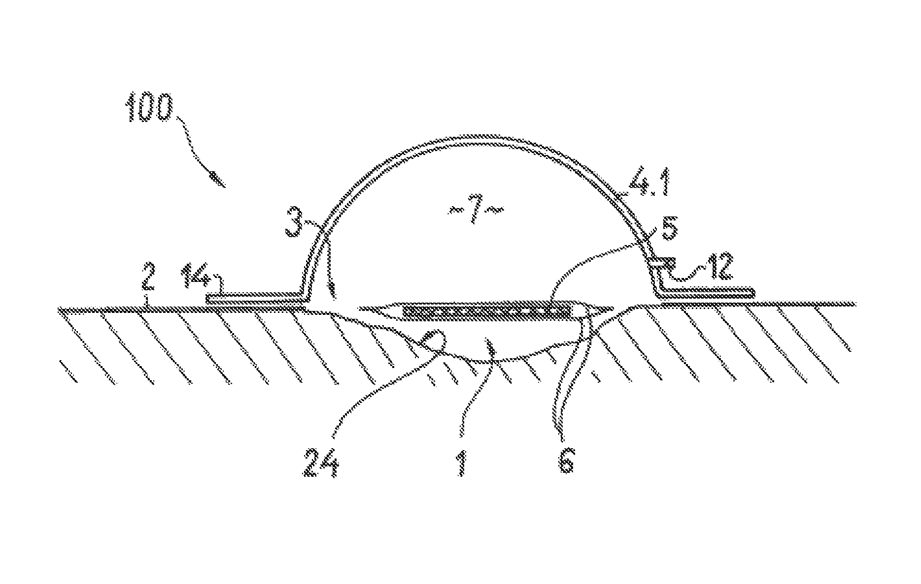
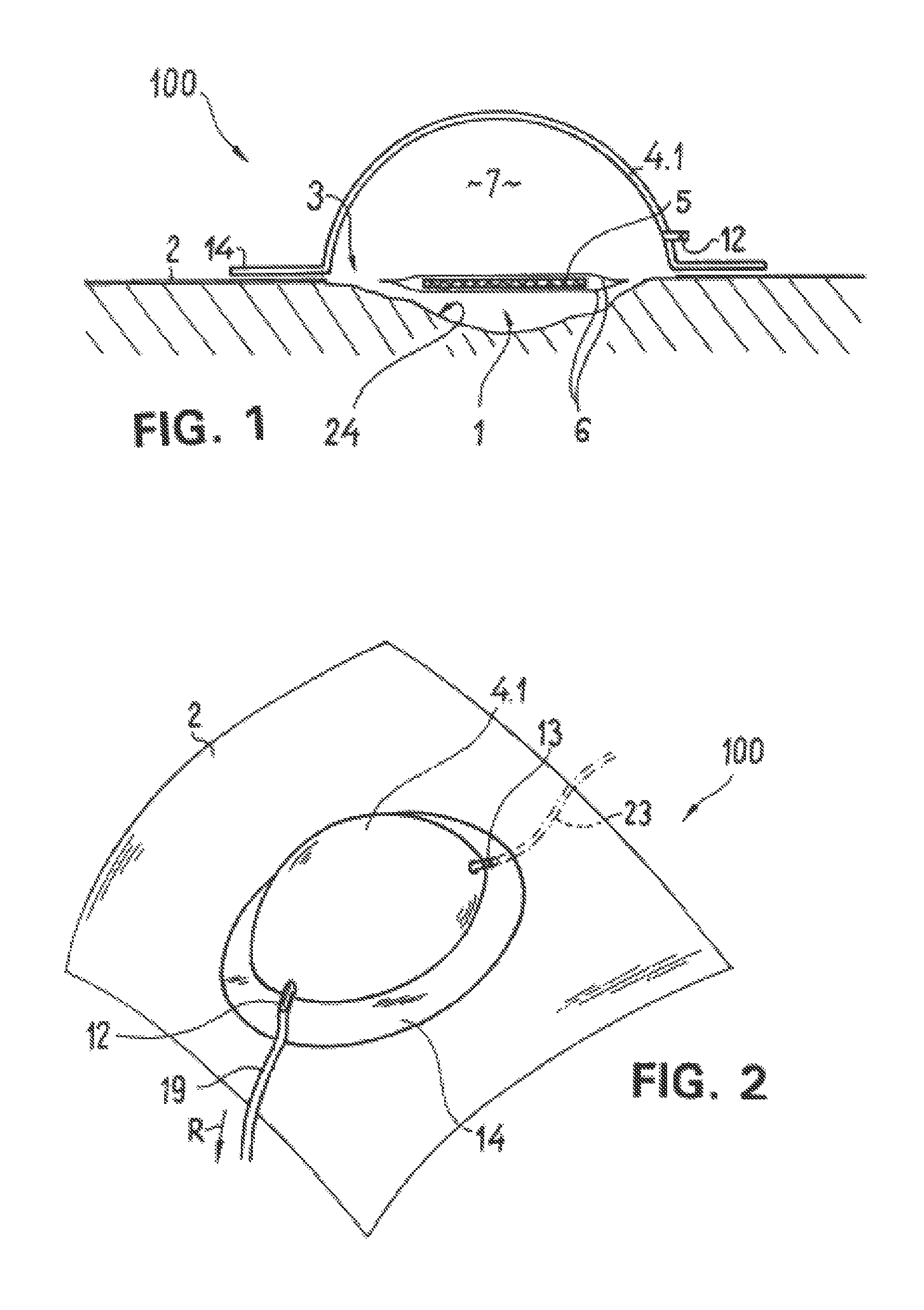
[0062]FIGS. 1 and 2 show a first embodiment (reference number 100) of the wound treatment device, consisting of a film-like wound cover element 2, a bell-shaped hollow body 4.1 and an absorption body 5. The hollow body 4.1 is made as a molded piece of polyethylene in the deep drawing process. The wall thickness of the translucent hollow body is 0.8 mm. The spherical molded piece passes into a peripheral flat collar 14, which is glued onto the wound cover element 2 by means of a medically safe adhesive. The wall of the hollow body bounds a cavity 7, which is in direct contact with a wound cavity 1 via an opening 3 made in the wound cover element 2. The wound cavity 1 is defined by a wound surface, designated as 24, and the wound cover element 2.

[0063]The hollow body 4.1 is provided with a one-way valve 12, which allows the flow through of air and—if necessary—excess wound secretions, if the hollow body is connected via an additionally provided conduit 19 to a corresponding mechanical...


PUM


Abstract

The invention relates to a wound treatment device with at least one elastically deformable vacuum-generating element which can be actuated directly by hand and which is arranged on and connected directly to a film-like wound-covering element that covers the wound chamber. The vacuum-generating element is a hollow body whose cavity, in the state with the device applied to the patient's body, communicates directly with the wound chamber via an opening formed on the wound-covering element. At least one absorption body that absorbs the wound secretions is positioned in the wound chamber and is surrounded by a finely porous sleeve that is permeable to liquid. The hollow body is provided with at least one valve.

Description

CROSS-REFERENCE TO RELATED APPLICATIONS[0001]This application is a continuation of application Ser. No. 12 / 096,264, filed Jul. 31, 2008, which application was a U.S. National Stage of International Application No. PCT / EP2006 / 012041, filed Dec. 14, 2006, and claims priority to German Patent Application No. DE 20 2005 019 670.3, filed Dec. 14, 2005.BACKGROUND OF INVENTION[0002]1. Field of Invention[0003]The invention concerns a wound treatment device with at least one elastically deformable vacuum producing element, which can be operated directly by hand, being arranged on a film-like wound cover element, covering the particular wound cavity, and being connected to the latter tubelessly.[0004]2. Description of Related Art[0005]A wound treatment device of the above mentioned kind is found in DE 198 44 355 A1. The vacuum producing element shown in FIG. 2 is glued directly to the wound cover film. The vacuum producing element is a bell-shaped hollow body, filled with a pre-compressed spo...

Claims


Application Information

Patent Timeline
Patent Type & Authority Patents(United States)
IPC IPC(8): A61M1/00A61F13/02A61M1/08A61M27/00A61F13/00
CPCA61M1/0088A61F13/0203A61F13/0209A61M1/0003A61M1/009A61M1/0009A61M1/0011A61M1/0072A61M1/08A61F13/00068A61F2013/0054A61F2013/00165A61F2013/00536A61F2013/00557A61M2205/075A61B90/05A61M1/82A61M1/962A61M1/984A61M1/96A61M1/64A61M1/92A61M1/684A61M1/985A61M1/67
Inventor RIESINGER, BIRGIT
Owner BSN MEDICAL GMBH & CO KG
Why Eureka
Try Eureka