
Polarizer devices and processes of manufacture

a technology of polarizers and manufacturing processes, applied in the direction of polarizing elements, paper/cardboard containers, instruments, etc., can solve the problems of low production yield of approximately 70%, woefully inefficient polarizers, and high cost to buyers, and achieve the effect of high efficiency and economics

Inactive Publication Date: 2016-05-03
FERNANDO PRIMAL +1
View PDF4 Cites 0 Cited by
  • Summary
  • Abstract
  • Description
  • Claims
  • Application Information

AI Technical Summary

Benefits of technology

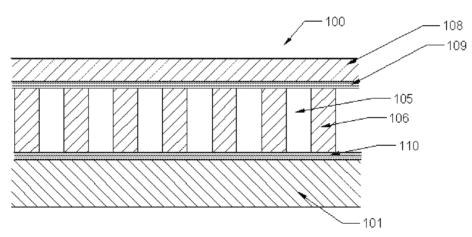
[0006]The polarizers and manufacturing processes described herein satisfy the above-described industry needs. According to the present invention, a mechanical polarizing device and the manufacturing process thereof are provided. The mechanical polarizer filters light in a highly efficient and economical manner equal to wire grid polarizers. The more economical, high performance, environmentally friendly mechanical polarizer device and manufacturing process described herein have significant benefits to manufacturers and consumers alike.
[0007]The polarizers produced according to the present invention are less expensive to produce and more effectively and efficiently control the transmittance of light, thereby eliminating the need for some of the additional layers within a liquid crystal device is provided. The polarizers and manufacturing processes described herein will accordingly reduce the manufacturing cost of liquid crystal devices, thus benefiting manufacturers and consumers. Further, a more efficient polarizer as described herein will also allow the use of a smaller or less intense back-light source which in turn will not only reduce the amount of heat generated by the device, but will also consume less energy, resulting in a device having overall greater energy efficiency and lower environmental impact (i.e., reduced carbon footprint).
[0008]The polarizer produced according to the present invention is produced with less toxic chemical elements than currently in use, thus reducing the overall environmental impact of polarizer production. The polarizers produced with the manufacturing processes described herein have no size limitations, unlike standard wire grid polarizers, and the process generates a higher quality and greater production yield. In addition, the polarizers produced as described herein are produced at a lower cost than a typical absorptive polarizer. In addition, the process produces a product with no or fewer adverse toxic impacts on the environment than current production methods.

Problems solved by technology

The materials and costs related to manufacturing these polarizers result in a high cost to the buyer.
In addition, the current manufacturing processes result in a very low production yield of approximately 70%.
Most polarizers are woefully inefficient and in an LCD application allow too much light to pass through, requiring the use of other layers to further reduce the amount of transmitted light.

Method used


Image

  • Polarizer devices and processes of manufacture
  • Polarizer devices and processes of manufacture
  • Polarizer devices and processes of manufacture

Examples


Embodiment Construction

Roll-Fed Process

[0038]This embodiment of the invention is the specification, design, development, assembly, fabrication, integration, testing and certification of a High Speed Roll-Fed Nano-Etching Production Facility (FIG. 7a), which will automate the entire thin film fabrication process.

[0039]The Nano-Etching Channel Grid Polarizer Device Production process will be setup either as a fully automated or semi-automated large-scale production line.

[0040]It will consist of multiple Reels, including, but not limited to:

[0041]a) A first Transparent Layer Supply Reel 124;

[0042]b) A first Adhesive Supply Reel 125;

[0043]c) A Non-Transparent layer Supply Reel 126;

[0044]d) A second Adhesive Supply Reel 127;

[0045]e) A second Transparent Layer Supply Reel 128; and

[0046]f) A Take-up Reel 129.

[0047]And an integrated multiple Stage Assembly, Fabrication and Inspection production line consisting of the following staging, processing and inspection elements and areas:

[0048]A. Cleaning and Preparation...


PUM

PropertyMeasurementUnit
heightaaaaaaaaaa
heightaaaaaaaaaa
widthaaaaaaaaaa

Abstract

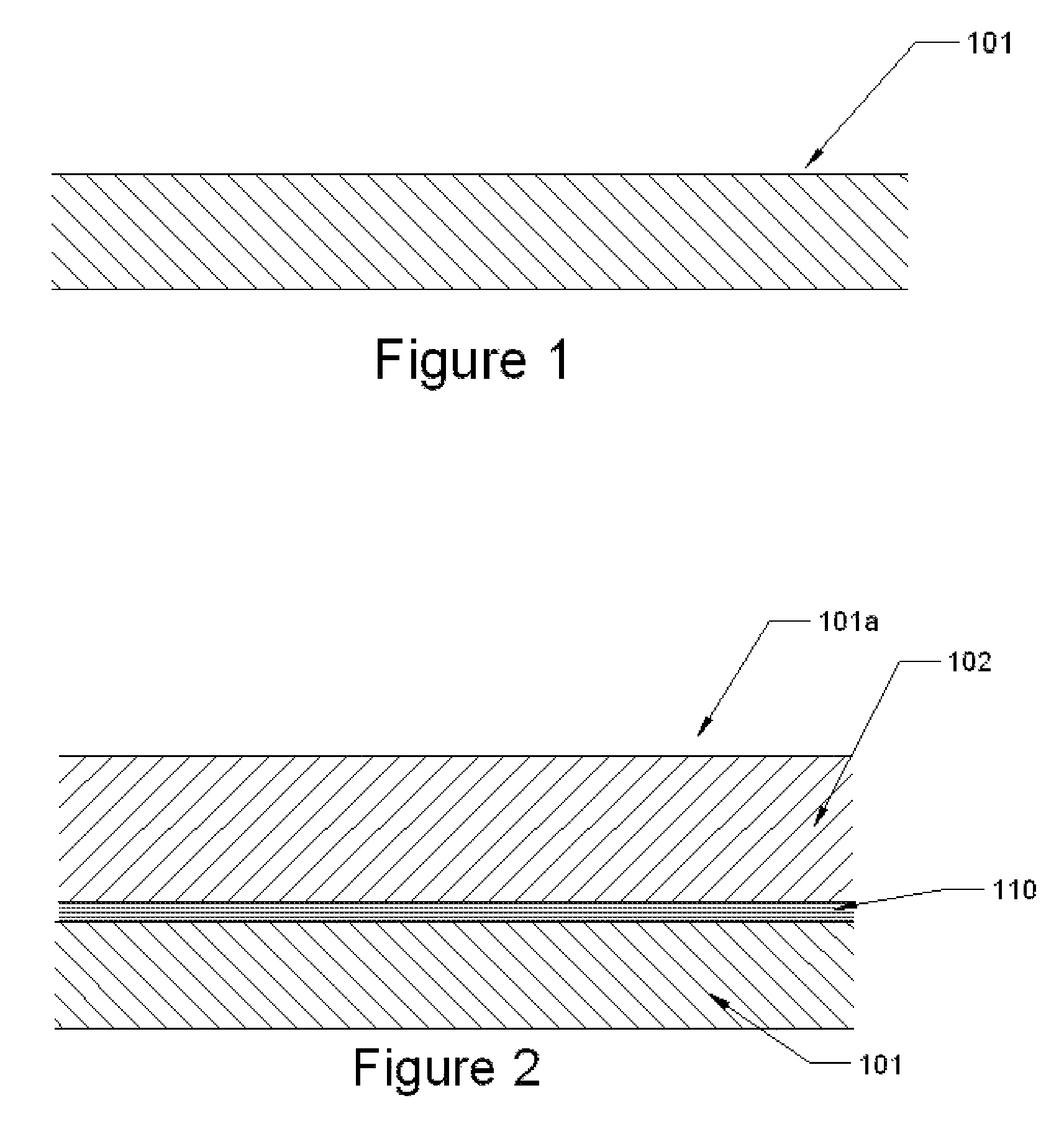
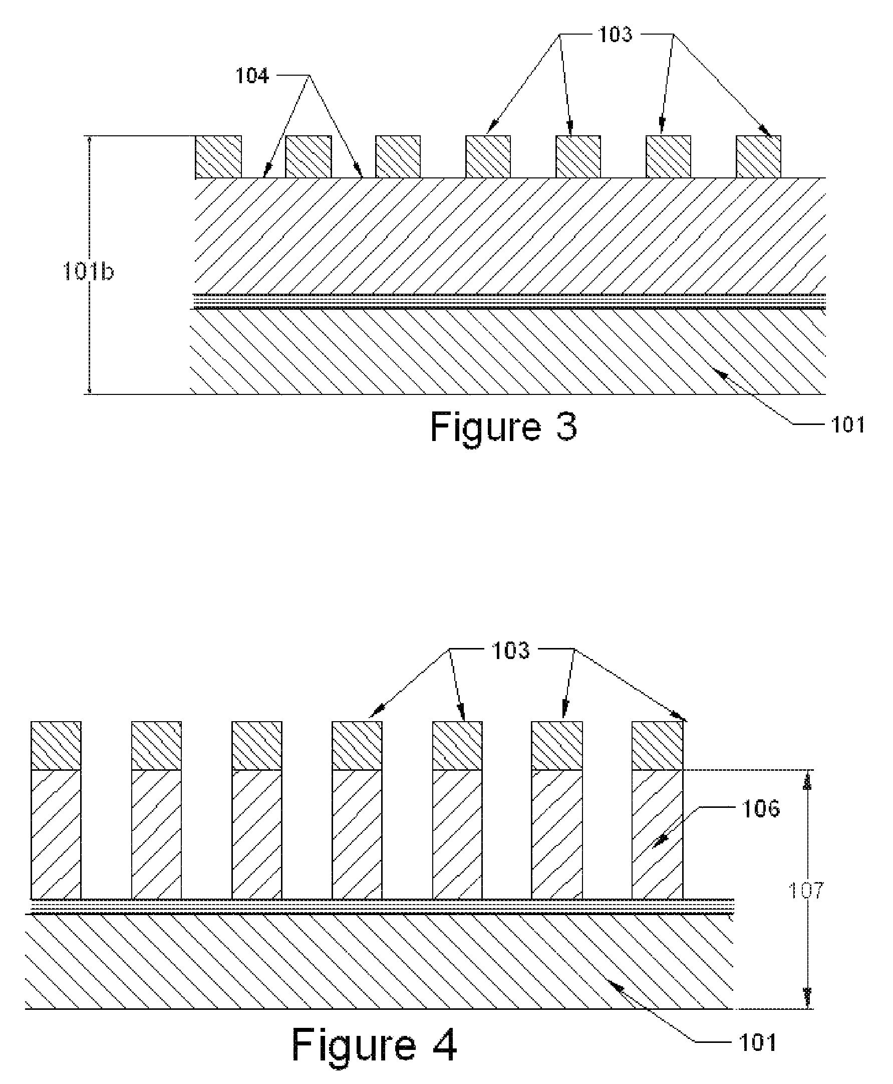
A simple and innovative process for manufacturing a high performance mechanical polarizing device is provided. The invention utilizes an inexpensive, high output production process where a transparent film substrate is coated with a non-transparent layer by deposition or other wet or dry method. Then a photoresist or a nano-imprint lithography process is used to overlay the non-transparent coated film with a pattern. The exposed non-transparent material is then removed by means of acid or base etching or the use of other mechanical or nano-technology removal methods. The photoresist is then removed and a protective layer may then be applied to the polarizer substrate. According to another embodiment, nano-imprinting techniques are used to prepare the polarizer substrate. The process may be automated in one or more embodiments, and lends itself to a high speed production manufacturing line, utilizing roll-to-roll, sheet fed or other methods of automated manufacturing.

Description

BACKGROUND OF THE INVENTION[0001]Polarizers play an important role in directing or rearranging light and are used in numerous applications from photography to liquid crystal displays (LCDs). Consumer demand for products that use polarizers has created an aggressive and competitive marketplace for manufacturers of large and small LCD devices, aircraft windows, medical imaging equipment, solar energy collectors and other applications not yet realized. In relation to LCDs, the performance of a polarizer determines not only the amount of transmitted light that reaches the viewer, but also the contrast of the viewing platform. The materials and costs related to manufacturing these polarizers result in a high cost to the buyer. In an effort to achieve an edge in the market, manufacturers are continually looking for lower cost polarizer components and construction and fabrication methods without sacrificing quality and performance.[0002]“Absorptive” polarizers, i.e., a linear polarizer whe...

Claims


Application Information

Patent Timeline
Patent Type & Authority Patents(United States)
IPC IPC(8): B32B38/10G02B5/30G02B5/02G02F1/1335
CPCB32B38/10G02B5/0268G02B5/3025G02B5/3058G02F1/133528G02F1/133536B32B2307/42Y10T156/10Y10T156/1039Y10T156/1062
Inventor FERNANDO, PRIMALFISCHER, STEVE
Owner FERNANDO PRIMAL
Learn More