Pro system using a hollow fiber membrane with superparamagnetic nanoparticle draw solution

a hollow fiber membrane and nanoparticle draw solution technology, applied in the field of pressure retarded osmosis (pro) system, can solve the problem of difficult osmotic pressure of the 40% ferrofluid solid side of the membrane, and achieve the effect of simple and efficient replacement of ferrofluid

Active Publication Date: 2016-05-10
AYLESWORTH TERRENCE W
View PDF7 Cites 6 Cited by
  • Summary
  • Abstract
  • Description
  • Claims
  • Application Information

AI Technical Summary

Benefits of technology

[0024]An array of hollow fiber membranes is submerged in an enclosed pure-water bath. A large number (100's to 1,000) of these hollow fiber membrane strands are grouped together into bundles and potted into membrane headers on the top and at the bottom of the pure-water enclosure. The fiber bundles are potted, or sealed into one of several top and bottom membrane headers such that the fiber lumen (the inside of the hollow fiber) is open to the inside of the membrane header and the pure feedwater is prevented from leaking into either the header or into the inside of a hollow fiber.
[0027]In an alternative design, each of the top and bottom membrane headers extends through a water-tight bulkhead fitting to the outside of the water-bath enclosure and is fitted with its own hydroturbine. This design has the advantage of reducing pressure loss (line loss) that would result in piping the pressurized fluid through the necessary header pipe length and elbows needed to transport the pressured fluid from individual membrane headers to a single effluent header and single hydroturbine. By fitting a hydroturbine on the end of each membrane header, the higher pressure fluid can be converted more directly into mechanical energy by the hydroturbine and correspondingly into electrical energy, at a point in the solution flow where the fluid is at a higher pressure. This leads to producing a greater amount of energy. Owing to the close spacing of the membrane headers and the relatively large size hydroturbine housing, alternating membrane headers extend through the bulkhead fitting to the outside of the pure-water enclosure. In this way, half of the hydroturbines, in an alternating fashion, are fitted to one side of the enclosure and half are fitted to the opposite side.
[0028]In yet another alternative design, each membrane bundle is potted directly into a membrane effluent pipe to a bulk-head fitting. The pipe would extend through a bulkhead fitting to a hydroturbine, with a hydroturbine for each membrane fiber bundle. A straight section of pipe from the membrane fiber bundle to the hydroturbine would provide the least amount of fluid friction and correspondingly, the lowest line loss to allow higher, more efficient electrical generation rates. Owing to the close spacing of fiber bundles and the relatively large hydroturbine housing, alternating membrane effluent pipes extend through the top of the pure-water enclosure, with the other half extending through its bottom. A service connection would be fitted to each membrane bundle on the opposite side of its hydroturbine to allow for nanoparticle removal and off-line service.
[0030]As each of these embodiments has the pressurized permeate / draw solution acting upon a hydroturbine that is outside of the water-bath enclosure, it is another object of the invention to prevent an electrical hazard from hydroturbine electrodes shorting out in the water solution.
[0032]To capitalize on the increased flux resulting from higher temperature feedwater, an electric powered water heater and a thermostat temperature control system has been engineered into this PRO apparatus. Since this PRO system is a closed system with no significant material input or output, it is economically permissible to control its temperature above ambient temperature. To maximize the return on investment of the cost of increasing the temperature, the system contains thermal insulation cladding around its entirety. An electrically powered water heater could be placed on the water return line after the magnetic field created by permanent magnets or electromagnets, just before the water is returned to the feed water side of the water-tight enclosure. The electric water heater is controlled by a thermostat and a bulk permeate water temperature probe located on the water-tight enclosure.
[0033]Separation and isolation of the ferrofluid furthermore, makes for simple and efficient replacement of the ferrofluid, by isolating, removing and replacing the magnetic nanoparticle isolation tank.

Problems solved by technology

The osmotic pressure of the 40% ferrofluid solids side of the membrane is more difficult because as a solid, a nanoparticle has no molecular weight, and hence no mole weight per unit liter.

Method used


Image

  • Pro system using a hollow fiber membrane with superparamagnetic nanoparticle draw solution
  • Pro system using a hollow fiber membrane with superparamagnetic nanoparticle draw solution
  • Pro system using a hollow fiber membrane with superparamagnetic nanoparticle draw solution

Examples


Embodiment Construction

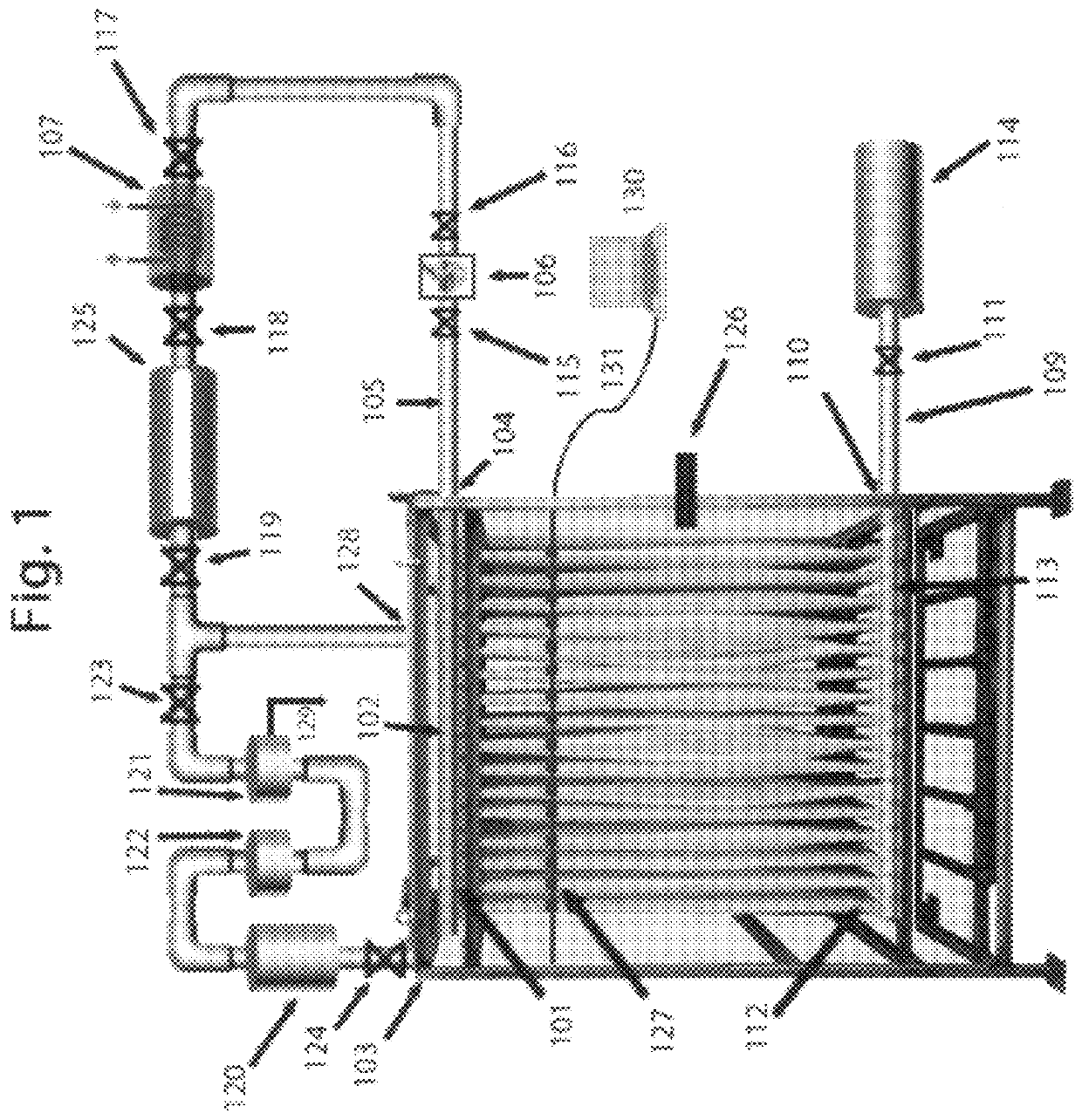
[0039]In FIG. 1, a pressure retarded osmosis (PRO) system is shown. It consists of a hollow fiber membrane system submerged in a pure water bath contained within a water-tight enclosure. ‘Pure water’ in this case means as close to perfectly pure water as economically feasible. With increasingly contaminated water (contaminated with suspended solids, dissolved solids, and possibly biological material), will come a reduction in the difference between the osmotic pressures of the solutions on either side of the membrane. With less difference between osmotic pressures, will come a lower net driving force, lower flux rates, and lower energy generation rates. And with increasingly pure water will come an increasingly expensive price tag. A ‘pure water bath’ would consist of de-ionized water, approximately 5 to 10 micromhos per centimeter (μmhos / cm, a measure of conductivity typically used measure concentrations of dissolved solids in water). It is anticipated that during operation, the wa...


PUM

PropertyMeasurementUnit
osmotic pressureaaaaaaaaaa
concentrationaaaaaaaaaa

Abstract

An array of hollow fiber membranes is grouped into bundles is submerged in an enclosed pure-water bath. The bundles are potted into top and bottom membrane headers such that the fiber lumen (the inside of the hollow fiber) is open to the inside of the membrane header and the pure feedwater is prevented from leaking into either the header or into the inside of a hollow fiber. Pure water penetrates the hollow fiber membrane. In accordance with pressure retarded osmosis (PRO) principles, the permeate and draw solution within the lumen are transported to at least one hydroturbine where electricity is generated. The draw solution contains superparamagnetic nanoparticles that are prevented from proceeding beyond a magnetic field. The system has a heater to improve its efficiency.

Description

BACKGROUND OF THE INVENTION[0001]This invention relates to a pressure retarded osmosis (PRO) system for the production of electricity. More particularly, it relates to a closed-loop, PRO system for creating a high pressure water flow that acts upon one or more hydroturbines generator to produce renewable, sustainable energy without a waste stream.[0002]Osmosis is the natural, universal and biologically ubiquitous movement of a solvent, such as water, through a selectively semi-permeable membrane from a region of low solute concentration solution to a region of comparably high solute concentration solution. The selectivity of the membrane allows for the passage of the solvent while preventing the passage of larger solute molecules through the relatively smaller membrane pores. The natural passage of water through a membrane is driven by the difference in the solute concentrations on either side of the membrane. The lower the solute concentration, the greater the driving force of its ...

Claims


Application Information

Patent Timeline
Patent Type & Authority Patents(United States)
IPC IPC(8): F01D15/10B01D63/02B01D61/00C02F1/44B01D61/02
CPCF01D15/10B01D61/002B01D61/005B01D61/027B01D63/02C02F1/442C02F1/445B01D2311/2607F03G7/005F03G7/015
Inventor AYLESWORTH, TERRENCE W.
Owner AYLESWORTH TERRENCE W
Why Eureka
Try Eureka