Electroplating method

a technology of electroplating and electrodes, applied in the direction of basic electric elements, electrical equipment, semiconductor devices, etc., can solve the problems of difficult to keep an appropriate current density at the anode, significant decrease in the metal ion concentration of the plating solution,

Active Publication Date: 2016-06-28
EBARA CORP
View PDF40 Cites 1 Cited by
  • Summary
  • Abstract
  • Description
  • Claims
  • Application Information

AI Technical Summary

Benefits of technology

[0011]When dissolution of a metal (metal ions) in a plating solution from a soluble anode takes place during electroplating, the current density at the anode is preferably kept in an appropriate range. This can prevent deterioration of an additive component(s) of the plating solution and can stably form a good-quality plated metal (plated film) on a surface of a substrate which serves as a cathode.
[0013]The present invention has been made in view of the above situation. It is therefore an object of the present invention to provide an electroplating method which can securely and efficiently fill a plated metal, such as copper, into deep high-aspect ratio vias in a bottom-up manner without producing defects, such as voids, in the plated metal to be embedded.
[0015]According to this electroplating method, a plating current is intermittently supplied between a substrate and an anode while repeating the supply and the stop of the plating current. During a current stop time when the supply of the plating current is stopped, a decrease in the metal ion concentration of the plating solution in the vicinity of the substrate, especially a shortage of metal ions in the bottoms of vias, can be eliminated by utilizing diffusion of ions in the plating solution towards the substrate caused by a concentration gradient of the ions. This can promote the bottom-up growth of plating. Further, according to this electroplating method, the plating current at a constant current value is intermittently passed between the substrate and the anode in such a manner that the proportion of the current supply time during which the plating current is supplied increases with the progress of plating. This makes it possible to keep an anode current density in an appropriate range during the supply of the plating current while controlling an average current density at a low level to prevent the formation of voids in the plated metal to be embedded in the vias, thus enabling good via-filling plating.
[0017]As a plated metal is gradually filled into vias with the progress of plating, the depth of the unfilled portion of each via gradually decreases, that is, the aspect ratio of the unfilled portion gradually decreases. Accordingly, filling of the plated metal into the vias can be performed efficiently by decreasing, with the progress of plating, a current stop time which is to supply metal ions, e.g., into the vias.
[0020]Filling of a plated metal into vias can be performed efficiently also by increasing the current supply time with the progress of plating.
[0024]The present invention makes it possible to securely and efficiently fill a plated metal, such as copper, into deep high-aspect ratio vias in a bottom-up manner without producing defects, such as voids, in the plated metal to be embedded.

Problems solved by technology

Especially when the vias are deep ones having a large aspect ratio, the metal ion concentration of the plating solution significantly decreases in the bottoms of the vias because of insufficient supply of metal ions by ion diffusion.
Thus, it is sometimes difficult to keep an appropriate current density at the anode.

Method used


Image

  • Electroplating method
  • Electroplating method
  • Electroplating method

Examples


Embodiment Construction

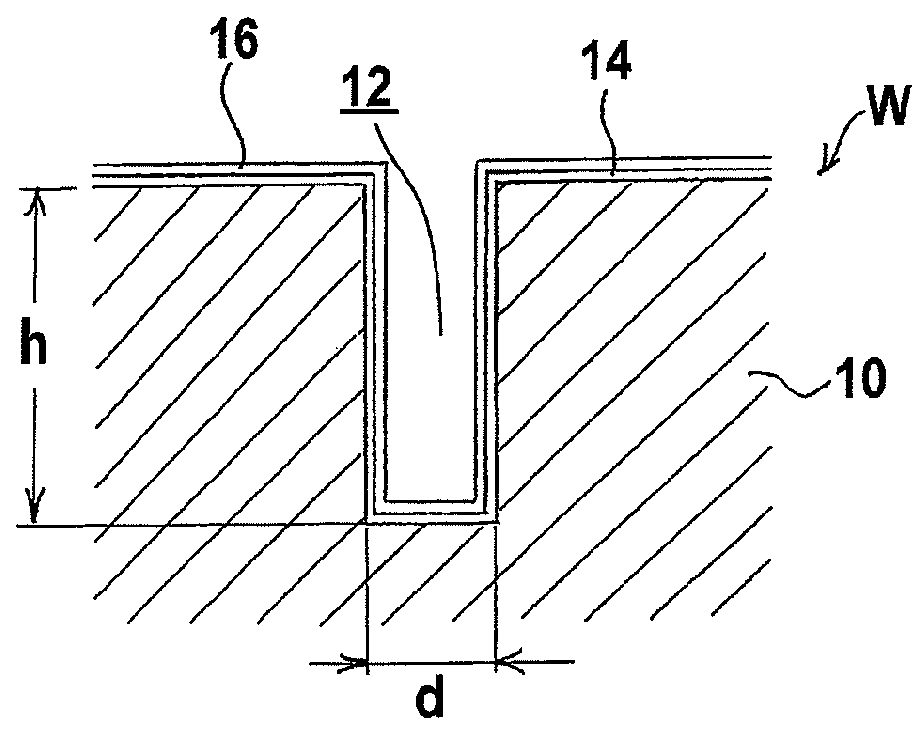
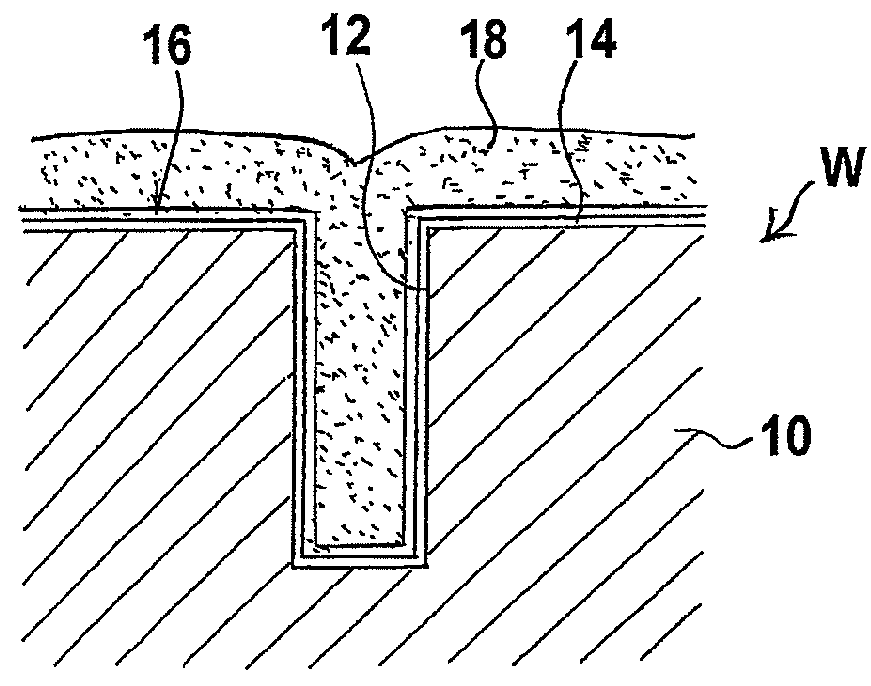
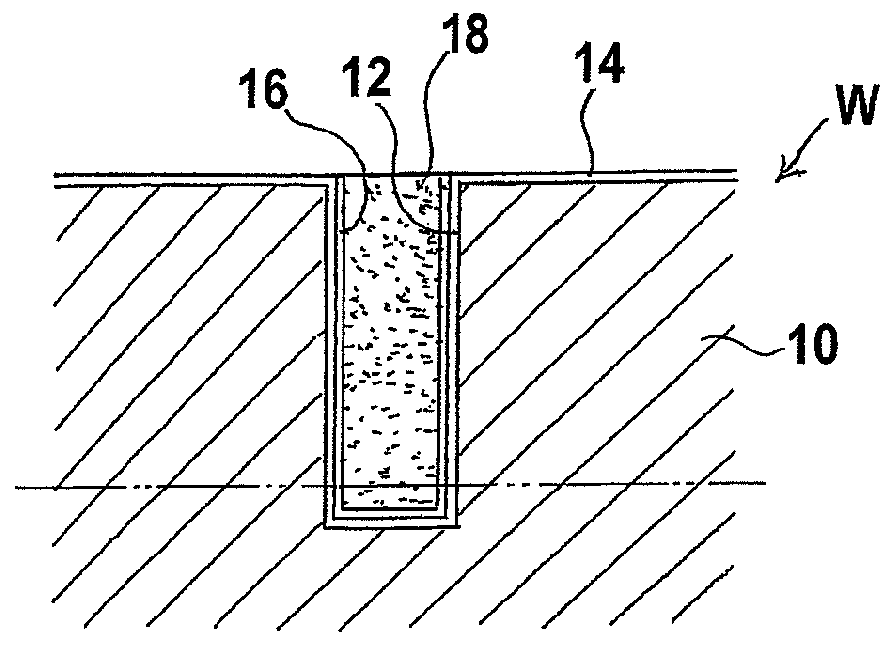
[0036]Preferred embodiments of the present invention will now be described with reference to the drawings. The following description illustrates an exemplary case where a substrate W, which has been produced by forming vias 12 in a surface of a base 10 such as a silicon wafer, forming a barrier layer 14 on an entire surface of the base 10, including surfaces of the vias 12, and then forming a copper seed layer 16 on the surface of the barrier layer 14, is prepared, as shown in FIG. 1A; and copper electroplating of the surface of the substrate W is carried out to fill the plated metal (copper) 18 into the vias 12, as shown in FIG. 1B.

[0037]FIG. 2 is an overall layout plan view of a plating facility for carrying out an electroplating method of the present invention. This plating facility is designed so as to automatically perform all plating processes including pretreatment of a substrate, plating, and post-treatment of the plating, in a successive manner. The interior of an apparatus...


PUM

PropertyMeasurementUnit
diameteraaaaaaaaaa
diameteraaaaaaaaaa
diameteraaaaaaaaaa

Abstract

An electroplating method can securely and efficiently fill a plated metal into deep high-aspect ratio vias in a bottom-up manner without producing defects in the plated metal. The electroplating method includes: immersing a substrate, having vias formed in a surface, and an anode in a plating solution in a plating tank, the anode being disposed opposite the surface of the substrate; and intermittently passing a plating current at a constant current value between the substrate and the anode in such a manner that the supply and the stop of the plating current are repeated, and that the proportion of a current supply time during which the plating current is supplied increases with the progress of plating, thereby filling a plated metal into the vias.

Description

BACKGROUND OF THE INVENTION[0001]1. Field of the Invention[0002]The present invention relates to an electroplating method, and more particularly to an electroplating method which is useful for filling a metal, such as copper, into vias in the manufacturing of a substrate, such as a semiconductor substrate or the like, which has a number of through-vias vertically penetrating in its interior, and which can be used in so-called three-dimensional packaging of semiconductor chips.[0003]2. Description of the Related Art[0004]A technique of forming through-vias of a metal such as copper, vertically penetrating through a semiconductor substrate, is known as a method to electrically connect the layers of a multi-layer stack of semiconductor substrates. FIGS. 1A through 1C show an exemplary process for producing a substrate having therein through-vias of copper. First, as shown in FIG. 1A, a substrate W is prepared by forming a plurality of upwardly-opening vias 12 in a base 10, such as a si...

Claims


Application Information

Patent Timeline
Patent Type & Authority Patents(United States)
IPC IPC(8): C25D5/18C25D7/12
CPCC25D5/18C25D7/123H01L21/2885H01L21/76898H01L21/288
Inventor YASUDA, SHINGOKURIYAMA, FUMIOSHIMOYAMA, MASASHINAGAI, MIZUKITAMARI, YUSUKE
Owner EBARA CORP
Why Eureka
Try Eureka