

Magnetic gradiometer and magnetic sensing method
a magnetic gradiometer and magnetic sensing technology, applied in the field of magnetometers, can solve problems such as never being discussed, and achieve the effect of improving the s/n ratio and high sensitivity measuremen
- Summary
- Abstract
- Description
- Claims
- Application Information
AI Technical Summary
Benefits of technology
Problems solved by technology
Method used
Image

Examples
example 1
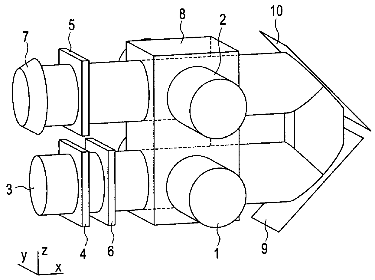
[0064]In FIG. 1, laser beams 1 and 2 for pumping, which are circularly-polarized beams, are generated from non-illustrated pump beam sources. The laser beams 1 and 2 propagate in parallel to each other in a positive y axis direction. Both are circularly-polarized beams in a same direction. A laser beam 3 for probe is generated from a non-illustrated probe beam source, a cell 8 contains alkali metal encapsulated therein. Polarizing plates 4 and 5 form a crossed nicol arrangement that does not transmit light when no polarization plane rotation occurs in the glass cell. A photodetector 7 receives the probe beam. Mirrors 9 and 10 turn the pump beam back. It is desirable that the mirrors have a high reflectivity for an incident angle of 45 degrees and are dielectric multilayer mirrors designed to reduce the difference in complex reflectivity between p wave and s wave. A faraday modulator 6 is driven by a modulation signal with a frequency ωF from a non-illustrated signal source to modula...
example 2
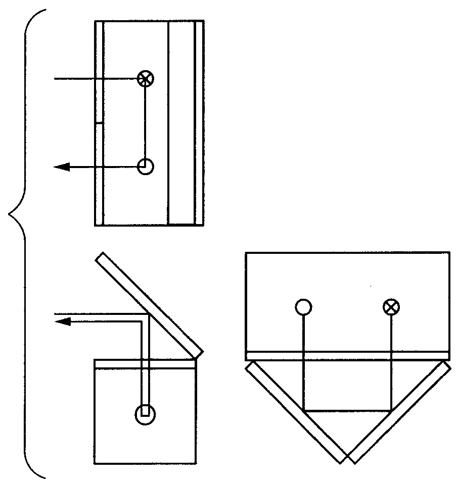
[0090]FIG. 4 illustrates another configuration of a gradiometer using magnetometers using a resonant operation. The second example is different from the first example in that no optical turn using mirrors is provided on an optical path of probe beam.
[0091]The second example is characterized in an arrangement in which a first pump beam 1 and a second pump beam 2, which correspond to two measurement regions, respectively, are circularly-polarized beams that rotate along a same direction but are incident on the cell 8 in directions opposite to each other, which is the difference from that of the first example. The circularly-polarized beams may have either right-hand rotation or left-hand rotation as long as the circularly-polarized beams rotate along the same direction. Furthermore, in the present example, there is a system that detects a rotation of a polarization plane by means of a balance photodetector including a polarization separation optical element 11 and photodetectors 12 an...
example 3
[0100]Another example in which rotations of a polarization plane of a probe beam by a magnetic field, which are measured in a first measurement region and a second measurement region, have directions opposite to each other will be described with reference to FIG. 6. In FIG. 6, a half-wave plate 14 is inserted between the first measurement region and the second measurement region along an optical path of the probe beam. A crystal axis direction of the half-wave plate 14 is made to correspond to a direction of a polarization plane of light passing through a polarizer 4. Where φ is a rotation of the polarization plane in the first measurement region, an angle of rotation of the polarization plane of the probe beam passing through the half-wave plate 14 is −φ. This is because change of a polarization state when the probe beam passing through the half-wave plate arranged as described above can be expressed by the following matrix where a set of electric field vectors (ex, ey)T is a base ...
PUM
 Abstract
Description
Claims
Application Information