Microcup compositions

a technology of micro-cups and compositions, applied in the field of micro-cups, can solve the problems of difficult peeling of the micro-cup layer from the substrate layer, the formation of the display panel is normally a very thin layer and therefore fragile, and the approach has its disadvantages

Active Publication Date: 2016-07-12
E INK CORPORATION
View PDF31 Cites 32 Cited by
  • Summary
  • Abstract
  • Description
  • Claims
  • Application Information

AI Technical Summary

Problems solved by technology

The display panel formed is normally a very thin layer and therefore fragile.
Once it is formed on a substrate layer, the microcup layer is very difficult to be peeled off from the substrate layer without causing damage to the structure.
However, this approach had its disadvantages.
For example, the formation of the microcups by microembossing could become difficult.
This is due to the fact that when pulling the mold from the partially cured microcups, with the presence of a release layer between the display panel and the substrate layer, the layers could be prematurely separated.
Moreover, the mold could also get stuck in the partially cured microcups to cause permanent damage to the mold.
However in this case, the thicker microcup bottom will cause more voltage drop at the microcup bottom, which likely leads to insufficient voltage for driving a display fluid contained within the microcups.
However, increasing the thickness of the walls will decrease the fill factor, resulting in unsatisfactory optical performance.

Method used


Image

  • Microcup compositions
  • Microcup compositions
  • Microcup compositions

Examples


example 2

Microcup Composition with Difunctional Components

[0107]21 Parts by weight of a binding agent for coating sold under EBECRYL® 8808 (Cytec), 39.7 parts of SR-602 (Sartomer), 25 parts of CD9038 (Sartomer), 4 parts of Silwet 7607 (Momentive), 9.86 parts of CN373 (Sartomer), 0.2 parts of 4-benzoyl-4′-methyldiphenylsulphide, and 0.24 parts of 2,4,6-trimethylbenzoyl diphenyl phosphine oxide were mixed homogeneously and used for the tensile test.

example 3

Tensile Test of Cured Microcup Materials

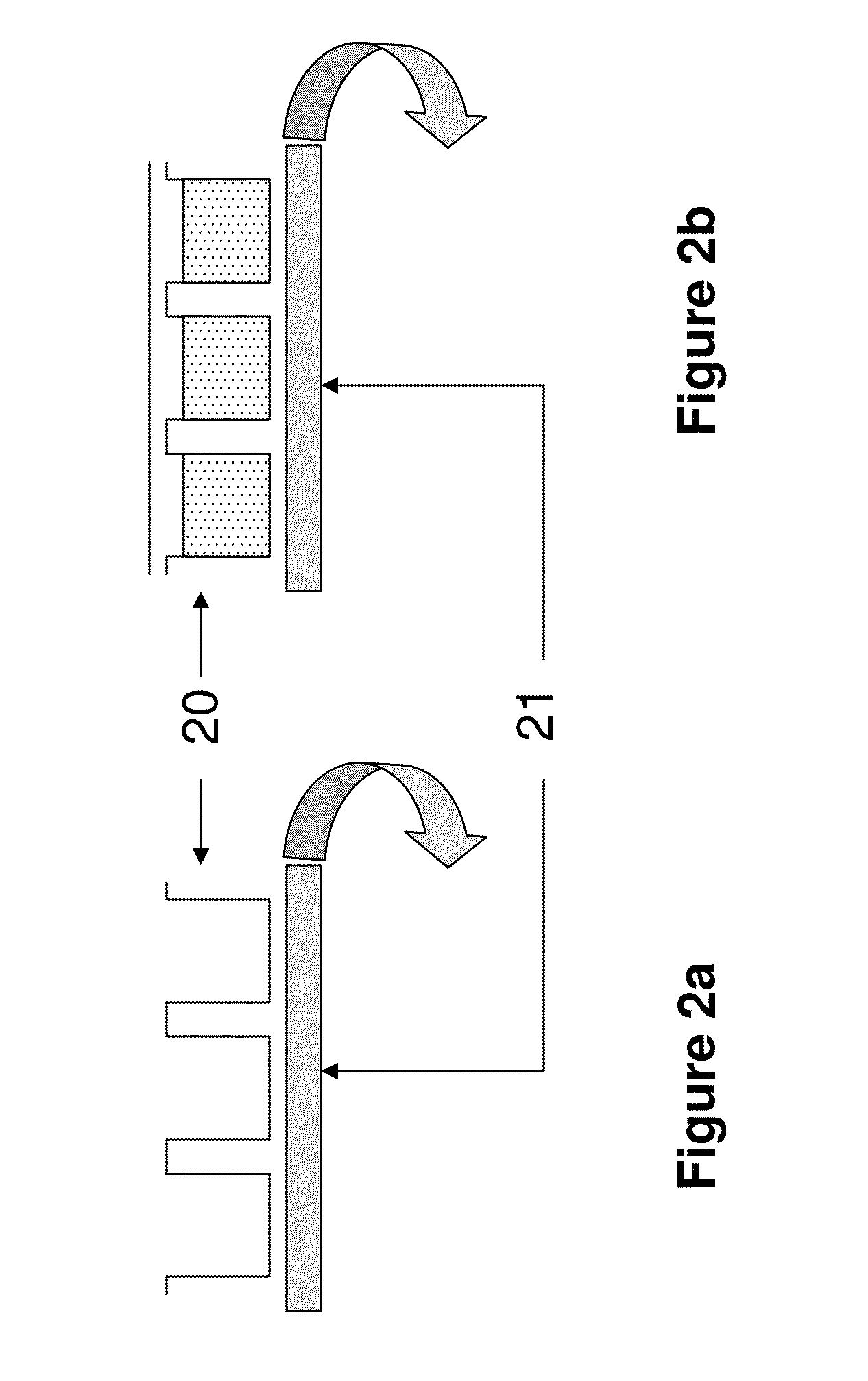
[0108]The microcup compositions of Examples 1 and 2 were coated onto 5 mil PET film with a targeted dry thickness of about 100 um, covered by PET release film, and then cured for 20 seconds under UV light at an intensity of 5 mW / cm2. The PET cover sheet was removed. The cured microcup layer was peeled off from the PET substrate and cut into stripes with a width of 1.25 cm and a length of 10 cm. The tensile test was then conducted by Instron at 50 mm / min. The results listed in Table 1 were the average of at least 5 measurements. The microcup composition containing difunctional components showed much improved elongation at break and toughness.

[0109]

TABLE 1Example 1Example 2Tensile Strength (N / m2)8.25 × 10⁶ 3.95 × 10⁶Elongation at Break (%)1.3122.86Toughness (J / m3)5.37 × 10645.43 × 106

example 4

Tensile Test of Panel

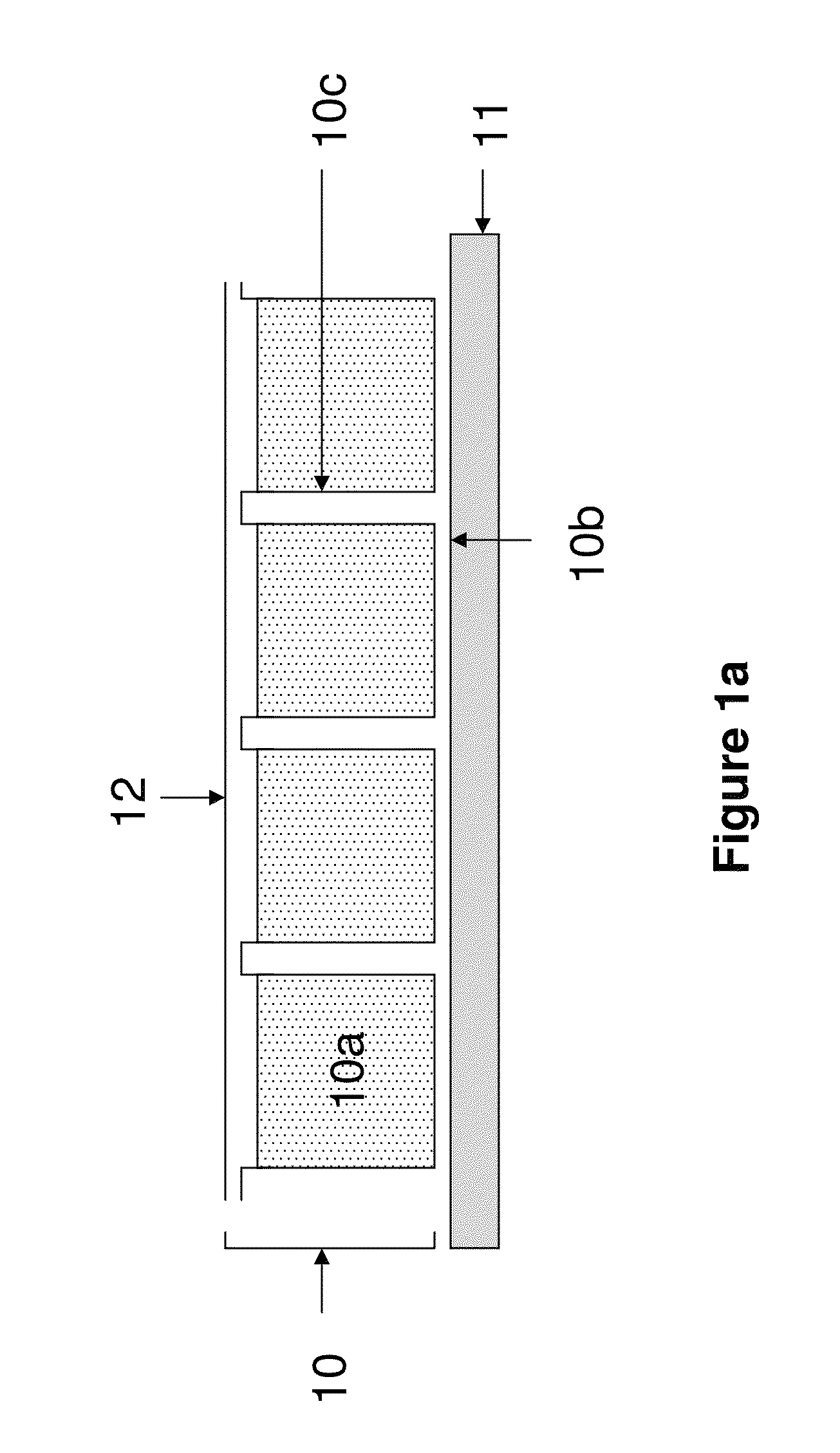
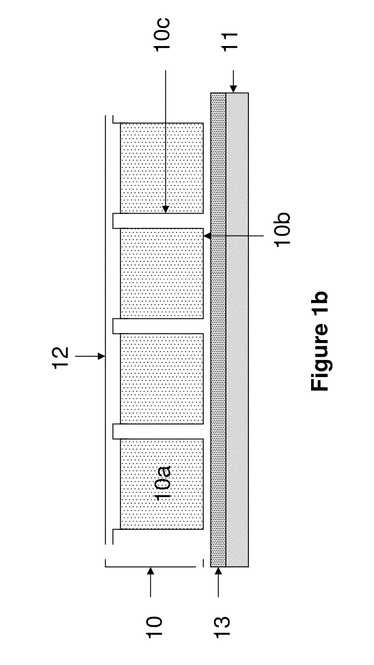
[0110]The microcup composition of Example 2 was used to prepare the microcup array with a thickness of around 27 um by microembossing according to U.S. Pat. No. 6,930,818. The electrophoretic fluid comprising charged pigment particles dispersed in a hydrocarbon solvent was coated onto the microcup array on a ITO / PET substrate film. The filled microcups are then sealed with a sealing layer with a thickness of around 17 um, following a one-pass procedure, according to U.S. Pat. No. 6,930,818. The microcup-based panel was then peeled off from the ITO / PET substrate film and subjected to the tensile test as described in Example 3.

[0111]The elongation was measured to be 18% before the microcup structure was damaged.

[0112]This same test could not be carried out with the microcup composition of Example 1 because the panel prepared from the composition of Example 1 could not be separated from the ITO / PET substrate film, without causing damages to the panel.


PUM

PropertyMeasurementUnit
elongation at breakaaaaaaaaaa

Abstract

The present invention is directed to a composition for preparing the microcups and the toughness of the display panel formed from such a composition may be significantly improved. In some cases, the panel may have an elongation at break of more than 10% and it can be completely peeled off from the substrate layer on which it is formed, without causing any damage to the panel.

Description

BACKGROUND[0001]U.S. Pat. No. 6,930,818 describes the microcup technology for forming a display panel. According to the patent, microcups may be formed by either a batchwise process or a continuous roll-to-roll process. A composition for forming the microcups is first coated on a substrate layer, followed by a microembossing or photolithographic method. A preferred process is microembossing by applying a male mold over the microcup composition to form microcups. The microcup composition can also be coated onto the male mold, followed by applying a substrate layer on top. The male mold may be released during or after the microcup composition is hardened.[0002]The display panel formed is normally a very thin layer and therefore fragile. Once it is formed on a substrate layer, the microcup layer is very difficult to be peeled off from the substrate layer without causing damage to the structure.[0003]Prior to the present invention, a release layer was considered to be added between a di...

Claims


Application Information

Patent Timeline
Patent Type & Authority Patents(United States)
IPC IPC(8): C09K19/00B32B27/16C08L33/06C08L33/14G02F1/167C09J133/14B32B27/06B32B7/12B32B7/06B29C59/02B29C39/02
CPCC08L33/06B32B7/06B32B7/12B32B27/06B32B27/16C08L33/14C09J133/14G02F1/167B29C39/02B29C2059/023B32B2307/20B32B2457/20B32B2457/202G02F2001/1672G09F9/372G02F1/1681A61K9/7084A61J1/16A61K9/7092
Inventor LI, YUZANG, HONGMEI
Owner E INK CORPORATION
Why Eureka
Try Eureka