
Imaging device and endoscope for detecting and displaying the shape of the micro-geometric texture of a transparent structure

a transparent structure and micro-geometric technology, applied in the field of image capture processors, can solve the problems of difficult to capture such a micro-geometric surface texture of objects based on shades, difficult to sprinkle liquid onto the mucosa in the first place, and difficulty in capturing such a micro-geometric surface texture based on shades, etc., to achieve the effect of enhancing the degree of polarization of the polarization degree image and enhancing the degree of polarization degree imag

Active Publication Date: 2016-07-12
PANASONIC INTELLECTUAL PROPERTY MANAGEMENT CO LTD
View PDF24 Cites 4 Cited by
  • Summary
  • Abstract
  • Description
  • Claims
  • Application Information

AI Technical Summary

Benefits of technology

The patent text describes a new image processing system and method that can capture images of transparent or translucent objects using an illuminating light beam. The system includes a light intensity image generator, a polarization degree image generator, a retouching section, and an image synthesizing section. The method involves generating a light intensity image, calculating the degree of polarization on a pixel-by-pixel basis, enhancing the polarization degree image at depressions on the object, and correcting its hue, saturation, and value. The technical effect of this invention is that it allows for easy capture of images with transparent or translucent objects that have a distinct micro-geometrical surface.

Problems solved by technology

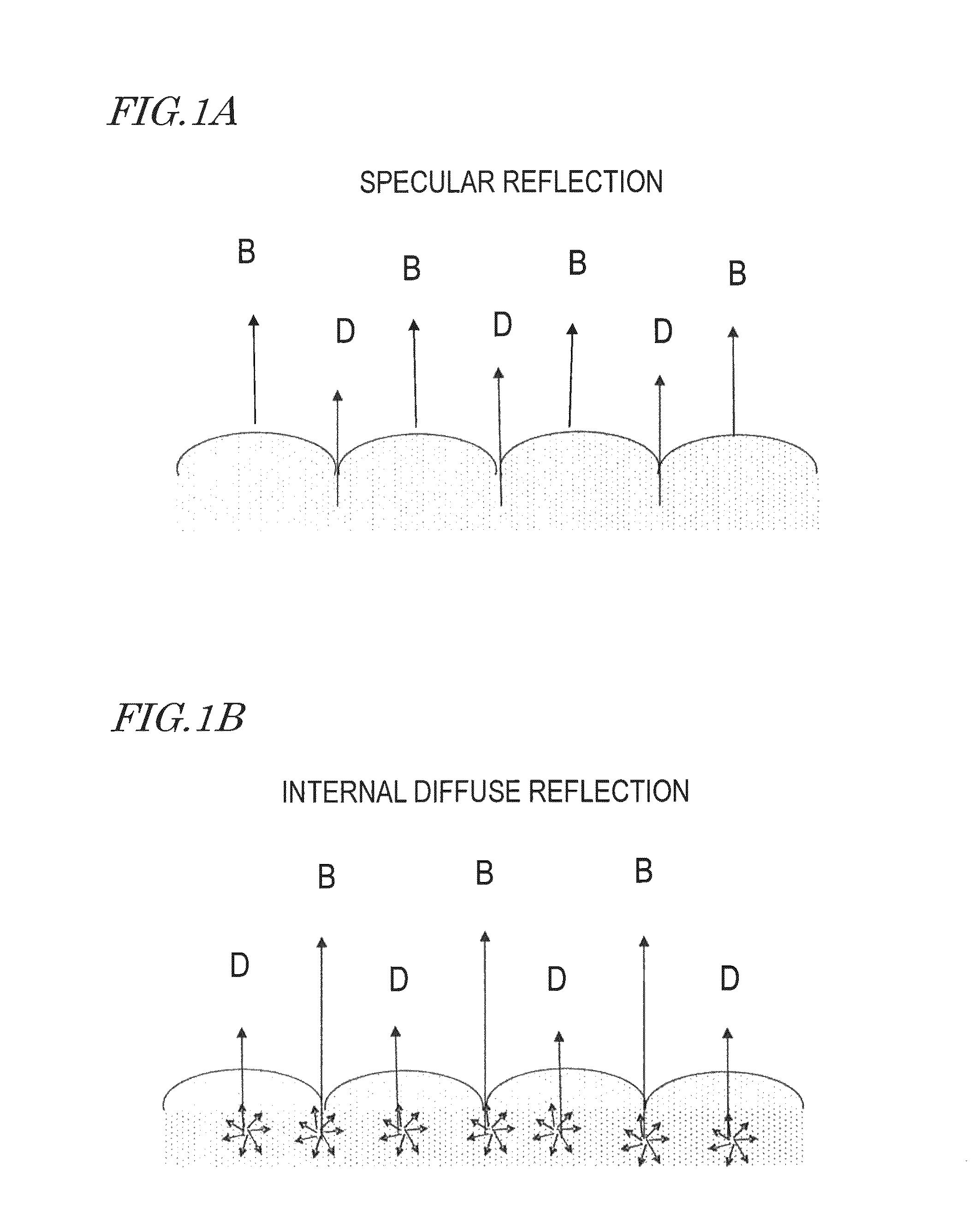
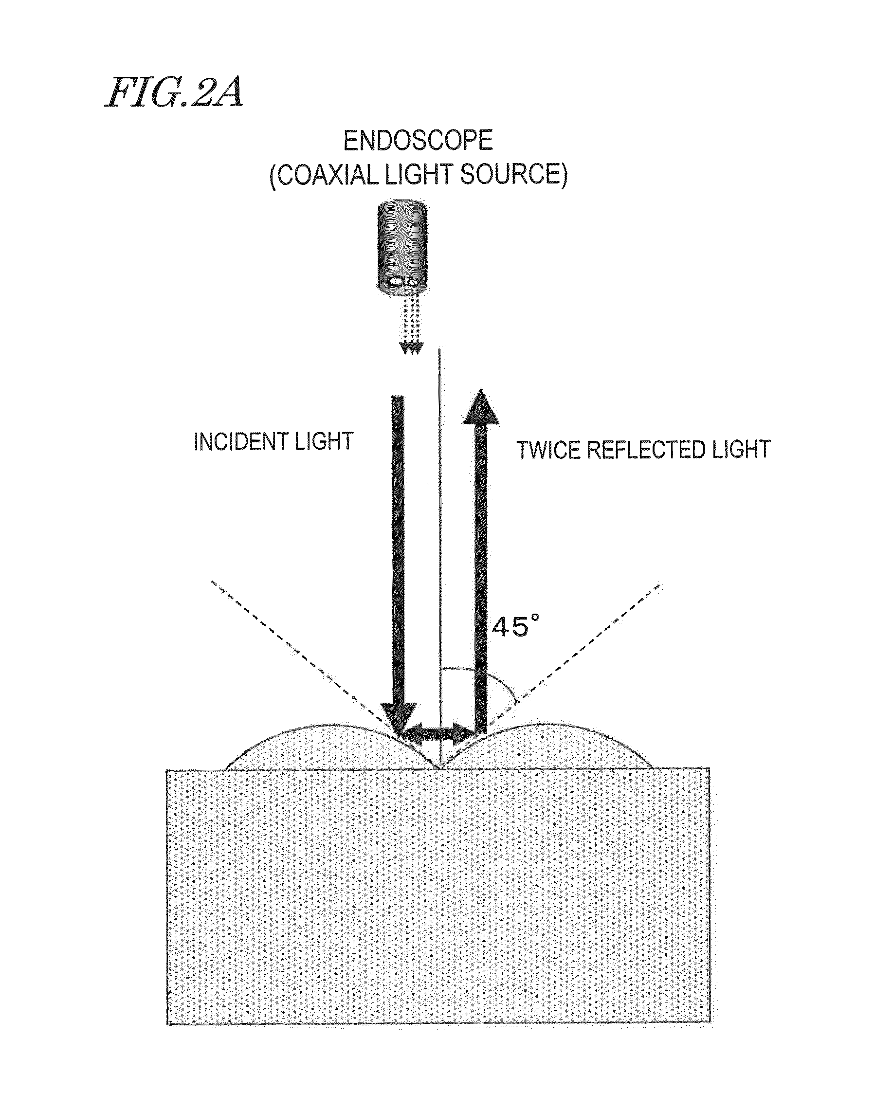
However, as will be described later, it is difficult to capture such a micro-geometric surface texture of the object based on the shades of the light intensity when the object is observed through an endoscope.
According to such an observation method, however, some liquid needs to be sprinkled onto the mucosa, and therefore, the object may bleed, the mucosa may change its color, and many other problems will arise.
On the other hand, when a so-called “capsule endoscope” which shoots an internal body tissue in water is used, it is impossible to sprinkle any liquid onto the mucosa in the first place.
According to any of these conventional techniques, however, it is difficult to detect and display the shape of the micro-geometric texture of a transparent or translucent mucosa.

Method used


Image

  • Imaging device and endoscope for detecting and displaying the shape of the micro-geometric texture of a transparent structure
  • Imaging device and endoscope for detecting and displaying the shape of the micro-geometric texture of a transparent structure
  • Imaging device and endoscope for detecting and displaying the shape of the micro-geometric texture of a transparent structure

Examples


embodiment 1

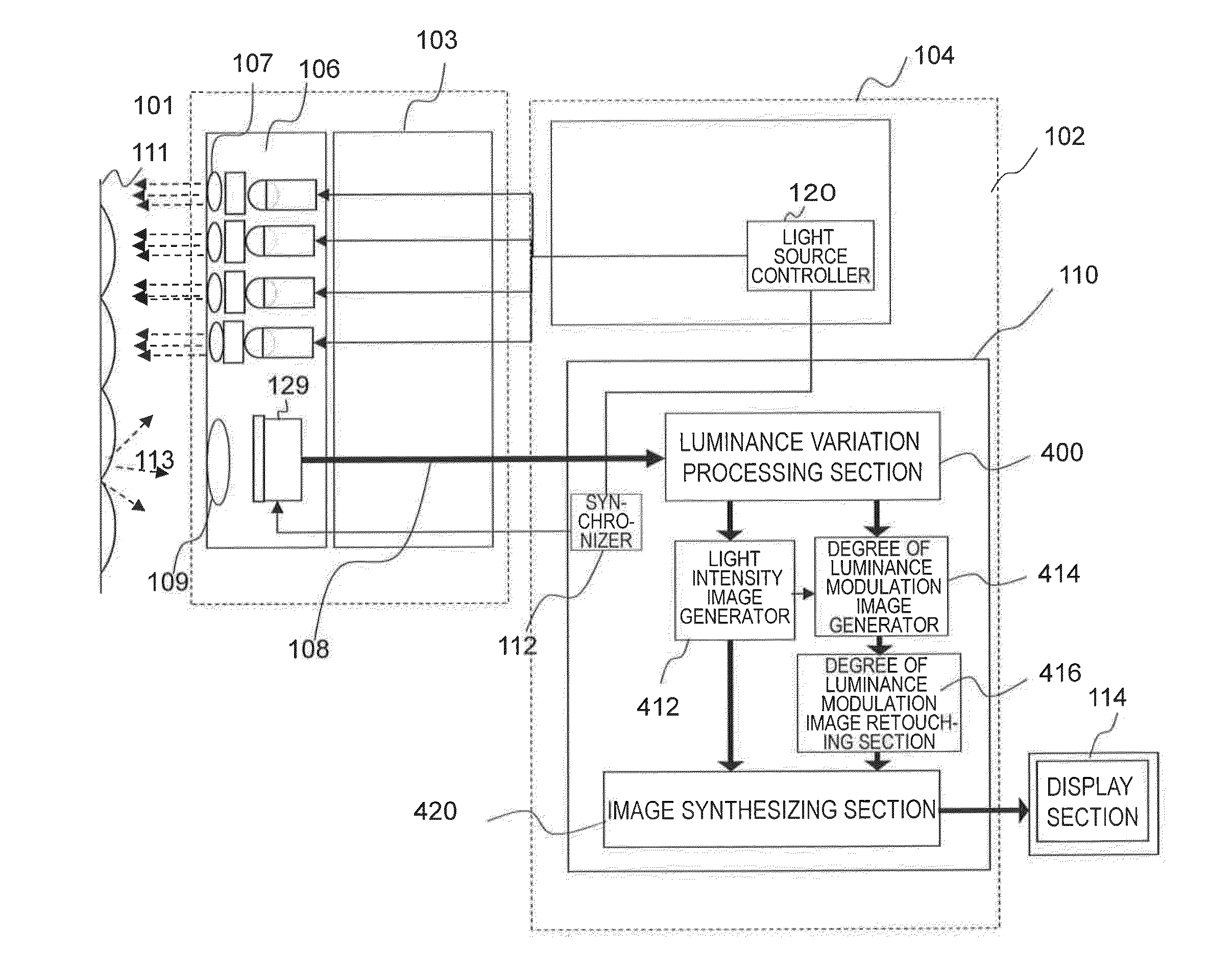
[0114]FIG. 5 schematically illustrates an overall configuration for an image capturing processor as a first embodiment of the present disclosure. This image capturing processor includes an endoscope 101, a controller 102 and a display section 114. The endoscope 101 includes a tip portion 106 with a monochrome broadband polarization image sensor 115 and an inserting portion 103 with a light guide 105 and a video signal line 108. The inserting portion 103 of the endoscope 101 has a structure that is elongated horizontally as shown in FIG. 5 and that can be bent flexibly. Even when bent, the light guide 105 can also propagate light.

[0115]The controller 102 includes a light source section 104 and an image processor 110. A lamp 108 such as a xenon lamp, a halogen lamp or an LED lamp is built in the light source section 104. The non-polarized white light emitted from the lamp 108 passes through a color wheel 116 with rotating RGB filters. As a result, red (R), green (G) and blue (B) frame...

embodiment 2

[0183]FIG. 21 schematically illustrates an overall configuration for an image capturing processor as a second embodiment of the present disclosure. In this second embodiment, a color image is captured by a single-chip color polarization image sensor 119 by irradiating the object with white light, which is a major difference from the first embodiment described above.

[0184]According to this embodiment, the non-polarized white light emitted from the light source section 104 is transmitted through the light guide 105 and irradiates the object with non-polarized white illuminating light 117. The light reflected from the object is observed by the color polarization image sensor 119. The rest of the processing is the same as what has already been described for the first embodiment, and description thereof will be omitted herein. Thus, the following description of the second embodiment will be focused on the configuration of the color polarization image sensor 119.

[0185]FIG. 22 illustrates ...

embodiment 3

[0198]FIG. 30 schematically illustrates an overall configuration for an image capturing processor as a third embodiment of the present disclosure.

[0199]According to this third embodiment, the object is irradiated with polarized light as illuminating light, and therefore, there is no need to use any polarization image sensor, which is a major difference from the first and second embodiments. Specifically, according to this embodiment, the object is irradiated with white light emitted from a polarization-rotating light source and a color image is captured using a single-panel color image sensor. An image is captured one by one by each of four polarized light sources, of which the polarization planes define mutually different angles. And by observing the variation in light intensity on a pixel-by-pixel basis, a pseudo-polarization image is captured.

[0200]Non-polarized white light beams emitted from four lamps 118 that are arranged in the light source section 104 are input sequentially ...


PUM


Abstract

In image capturing processor in one embodiment comprises: an image capturing section including an image sensor that captures a polarization image of an object being illuminated with an illuminating light beam; and an image processing section. The image processing section has: a light intensity image generator which generates a light intensity image based on the output of the image sensor; a polarization degree image generator which generates a polarization degree image by calculating the degree of polarization on a pixel-by-pixel basis; a retouching section which generates a retouched polarization image by enhancing the degree of polarization of the polarization degree image at depressions on a micro-geometric surface of the object and by correcting at least one of its hue, saturation and value; and an image synthesizing section which synthesizes the retouched polarization image and the light intensity image together.

Description

[0001]This is a continuation of International Application No. PCT / JP2013 / 001675, with an international filing date of Mar. 13, 2013, which claims priority of Japanese Patent Application No. 2012-116796, filed on May 22, 2012, the contents of which are hereby incorporated by reference.BACKGROUND[0002]1. Technical Field[0003]The present application relates to an image capturing processor which can obtain information about the surface topography of a translucent object or any other substance which is usually difficult to observe using only light intensity (luminance) information, and also relates to an endoscope which can be used to observe the surface of an organ.[0004]2. Description of the Related Art[0005]An image is captured through an endoscope by illuminating the wall surface of an organism's organ which is covered with a mucosa with light. When an organ is observed through an endoscope, not only a variation in the surface color of the object but also its micro-geometric surface ...

Claims


Application Information

Patent Timeline
Patent Type & Authority Patents(United States)
IPC IPC(8): H04N7/18H04N5/225G01J4/04H04N9/04H04N5/235A61B1/00A61B1/05A61B1/07G01J1/02G01J1/04
CPCH04N7/18A61B1/00186A61B1/05A61B1/051A61B1/07G01J1/0209G01J1/0411G01J4/04H04N5/2254H04N5/2256H04N5/2354H04N9/045H01L27/14627H04N23/555H04N23/56H04N23/74H04N25/134
Inventor KANAMORI, KATSUHIROMATSUNO, TOSHINOBU
Owner PANASONIC INTELLECTUAL PROPERTY MANAGEMENT CO LTD
Learn More