Hydropneumatic piston/cylinder arrangement

a technology of hydraulic piston and cylinder, applied in the direction of spring/damper, liquid based damper, shock absorber, etc., can solve the problems of a1, not suitable for all applications, high installation space required, response of suspension subject to hysteresis and time lag, etc., to achieve high operational reliability in long-term operation

Active Publication Date: 2016-07-19
HYDAC TECH GMBH
View PDF20 Cites 0 Cited by
  • Summary
  • Abstract
  • Description
  • Claims
  • Application Information

AI Technical Summary

Benefits of technology

[0004]An object of the present invention is to provide an improved hydropneumatic piston / cylinder arrangement characterized by a high operational reliability in long-term operation despite its compact design.
[0005]According to the invention, this object is basically achieved by a hydropneumatic piston / cylinder arrangement having a piston element provided as the spring element. Its accumulator piston is directly adjacent to the hydraulic fluid in the cylinder chamber. When the piston accumulator is integrated into the cylinder, this arrangement eliminates the external components that take up installation space, such as those which are necessary in an external spring element. Also, the integrated piston accumulator yields a much greater operational reliability in comparison with a bladder accumulator, with regard to preventing gas diffusion through a diaphragm material and with regard to the greater mechanical sturdiness in comparison with an accumulator diaphragm.
[0008]The fluid passage in the intermediate body may be provided in the form of a through-hole dimensioned for the volume flows that are provided accordingly. Alternatively and preferably in addition to the through-hole, a fluid passage in the form of a throttle check valve may be provided in the intermediate body. This valve yields the possibility of designing the volume flows created with the piston movements to be different in one stroke direction and in the other stroke direction. Rapid damping in one stroke direction is then induced with a throttled reverse movement accordingly. This arrangement also dissipates vibration in the system.
[0011]For an additional throttle effect, independently of the piston connected to the piston rod in the tension direction and in the compression direction, a throttle check valve can be provided in the piston, permitting a limited fluid flow from the front side of the piston to the rear side of the piston adjacent to the piston rod, i.e., to a chamber closed on the cylinder end, i.e., to a closed chamber situated at the end of the cylinder from which the piston rod extends out of the cylinder with a seal.

Problems solved by technology

Known approaches, such as that disclosed in DE 35 12 232 A1, are not suitable for all applications.
Due to the external gas or spring mechanisms plus the respective control system, the required installation space is accordingly high, and the response of the suspension is subject to a hysteresis and a time lag because of the long control distances via the aforementioned valves plus the inlet and outlet lines.
This approach is disadvantageous inasmuch as operational reliability is not ensured in long-term operation because the permeability of the material of the diaphragm of the bladder accumulator results in loss of gas from the bladder accumulator via diffusion.
The measures described in the Japanese document to prevent gas diffusion by coating the diaphragm with an amorphous carbon layer are complex and do not offer absolute protection against gas diffusion through the membrane.

Method used


Image

  • Hydropneumatic piston/cylinder arrangement
  • Hydropneumatic piston/cylinder arrangement
  • Hydropneumatic piston/cylinder arrangement

Examples


Embodiment Construction

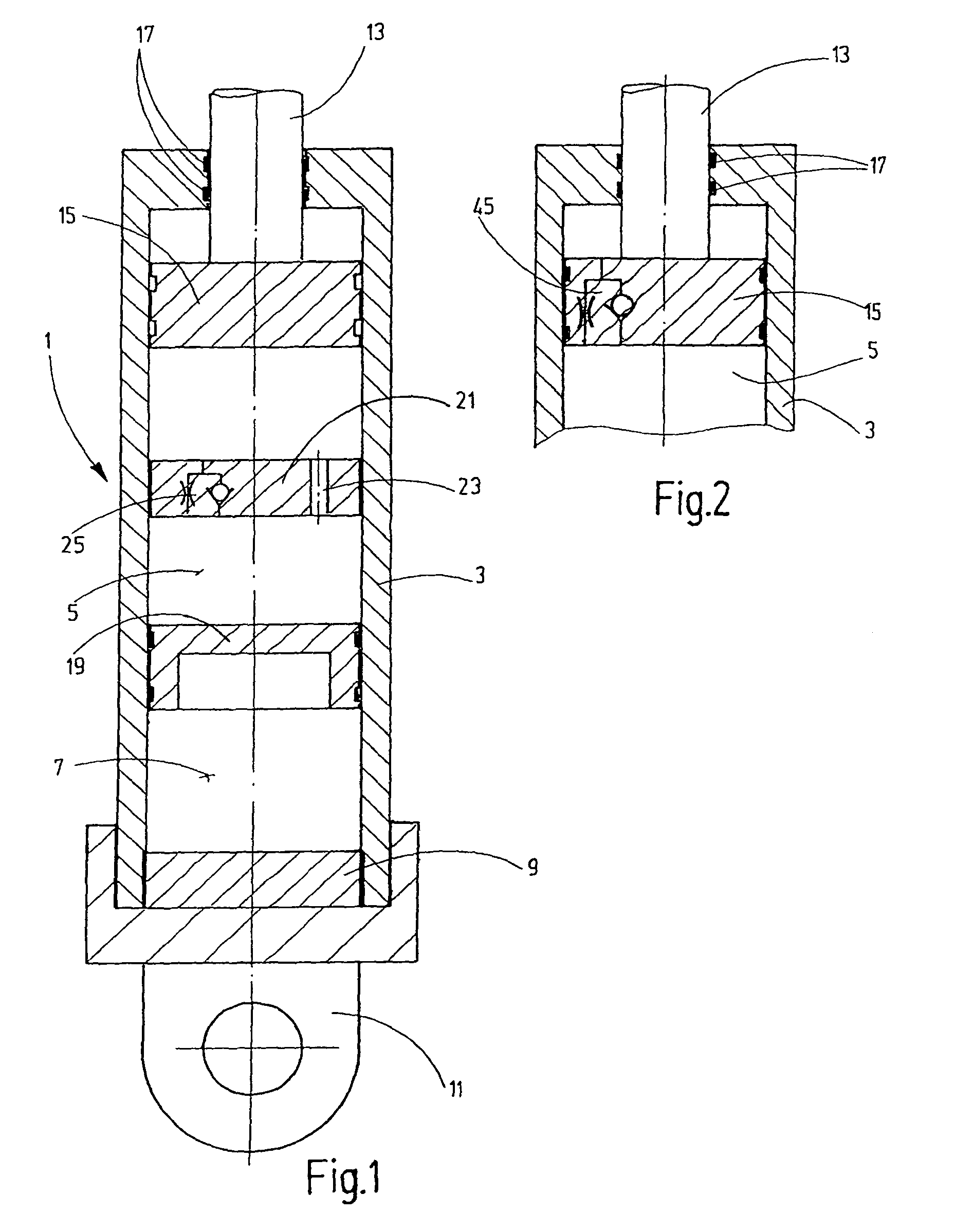
[0018]In the exemplary embodiments shown in the drawings, the cylinder 1 is in the form of a cylinder liner 3 extending seamlessly from the cylinder chamber 5, forming the fluid side, to the spring accumulator 7 that is integrated into the cylinder liner 3. On the lower end in FIG. 1 belonging to the spring accumulator 7, the cylinder liner 3 is sealed by a closing plate 9 that is bolted or welded in place. A corresponding filling connection located in the closing plate 9 for filling the spring accumulator 7 with working gas (e.g., N2) is not shown in the simplified diagram in FIG. 1. On the end having the closure cap 9, a fastening eye 11 is welded or bolted onto the cylinder liner 3. The piston rod 13 of a main piston 15 is movable in the cylinder chamber 5 on the fluid side and passes through the opposite closed upper end of the cylinder liner 3 with a fluid-tight seal formed by sealing elements 17. The spring accumulator 7 is formed on the piston accumulator that has an accumula...


PUM


Abstract

A hydropneumatic piston / cylinder arrangement, in particular for use as a spring element and / or shock absorber element, includes a cylinder (1) and a piston (15) axially movable in the cylinder chamber (5) of the cylinder. The cylinder chamber is filled with hydraulic fluid. The piston (15) is connected to a piston rod (13) extending outwardly in a sealed manner from one end of the cylinder (1). The base of the piston remote from the piston rod (13) can be operatively connected to a pneumatic spring mechanism (7) to convey fluid. A piston accumulator (7) has an accumulator piston (19) directly adjoining the hydraulic fluid in the cylinder chamber provided as the spring mechanism.

Description

FIELD OF THE INVENTION[0001]The invention relates to a hydropneumatic piston / cylinder arrangement, in particular for use as a spring element and / or as a shock absorber element, comprising a cylinder and a piston. The piston is axially movable in the cylinder chamber of the cylinder. The cylinder chamber is filled with hydraulic fluid. The piston is connected to a sealed piston rod extending outwardly from one end of the cylinder. The base of the piston facing away from the piston rod can be brought into fluid-conducting operative connection with a pneumatic spring mechanism.BACKGROUND OF THE INVENTION[0002]Such hydropneumatic piston / cylinder arrangements are known; see, for example, Japanese Patent Publication 2006070950A. Such piston / cylinder arrangements may be used for various applications, for example, in vehicles, in particular in commercial vehicles, for the axle suspension, or in general technology as vibration dampers or shock absorbers or the like. A compact design of the p...

Claims


Application Information

Patent Timeline
Patent Type & Authority Patents(United States)
IPC IPC(8): F16F9/06
CPCF16F9/061F16F9/067
Inventor WEBER, NORBERT
Owner HYDAC TECH GMBH
Why Eureka
Try Eureka