
Flexible LED light source panel, and flexible LED lighting device for taking image by using the same panel

a technology of led lighting and led light source, which is applied in the direction of lighting support devices, light source combinations, instruments, etc., can solve the problems of limited mobility and storage capacity of products, difficult to emit heat, and limit the weight of products, etc., to achieve excellent heat radiation characteristics and enhance the mobility and storage of lighting devices.

Active Publication Date: 2016-07-19
F J WESTCOTT
View PDF15 Cites 3 Cited by
  • Summary
  • Abstract
  • Description
  • Claims
  • Application Information

AI Technical Summary

Benefits of technology

The present invention provides a flexible LED light source panel that is portable, storable, and has good heat dissipation. Additionally, a flexible LED lighting device that can take pictures and has various functions is provided. The control module enables the LED module to work with a camera shutter, and the lens-free and lens-attached LEDs can warm up and emit light based on an input signal. The telescopic rib made of spring steel or plastic with excellent elasticity is used. The technical effects of the invention are improved mobility, flexibility, and heat radiation of the LED lighting device, as well as improved image quality and various functions.

Problems solved by technology

However, a typical LED device for an image needs high power light for its characteristic, and in order to overcome such a limitation, the typical LED device further needs a heat radiation structure and thus there is a limitation in which the weight of a product increases.
However, since a flexible structure disclosed in the application has a limitation in achieving high power lighting when a branch or line type LED light source module is applied or implemented, a separate heat radiation structure is needed in order to satisfy a characteristic as image lighting and thus there is a limitation in the mobility and storage capability of a product.
Also, when heat radiation fabric is used as the heat radiation structure in order to improve the mobility and storage of the product, special heat radiation processing is needed, and when general fabric is used, it is difficult to emit heat from the LED because a phenomenon that the fabric absorbs heat, and thus there is a limitation in that heat is accumulated in the fabric.
In recent, a lighting device using an LED that may replace these lighting devices is emerging, but as a configuration is provided to be suitable for various characteristics as described above and a heat radiation plate is provided in order to emit heat from a high-power LED, there is a limitation in that the weight of the product increases.
Also, there are limitations in that a continuous-light lighting device may not provide a flash effect and a diffused, continuous light lighting device generates shade when being used to produce focused light.
Also, since the complexity and weight of a structure for applying various functions increase, there is a need for a lighting device that has a structure easy to carry, store and move.

Method used


Image

  • Flexible LED light source panel, and flexible LED lighting device for taking image by using the same panel
  • Flexible LED light source panel, and flexible LED lighting device for taking image by using the same panel
  • Flexible LED light source panel, and flexible LED lighting device for taking image by using the same panel

Examples


Embodiment Construction

[0053]Embodiments of the present invention are described below in detail with reference to the accompanying drawings so that a person skilled in the art may easily practice the present invention. However, the present invention may be implemented in many different forms and is not limited to embodiments that are described herein. Content irrelevant to descriptions is omitted in order to clearly describe the present invention clear, and same or similar components have similar reference numerals throughout the disclosure.

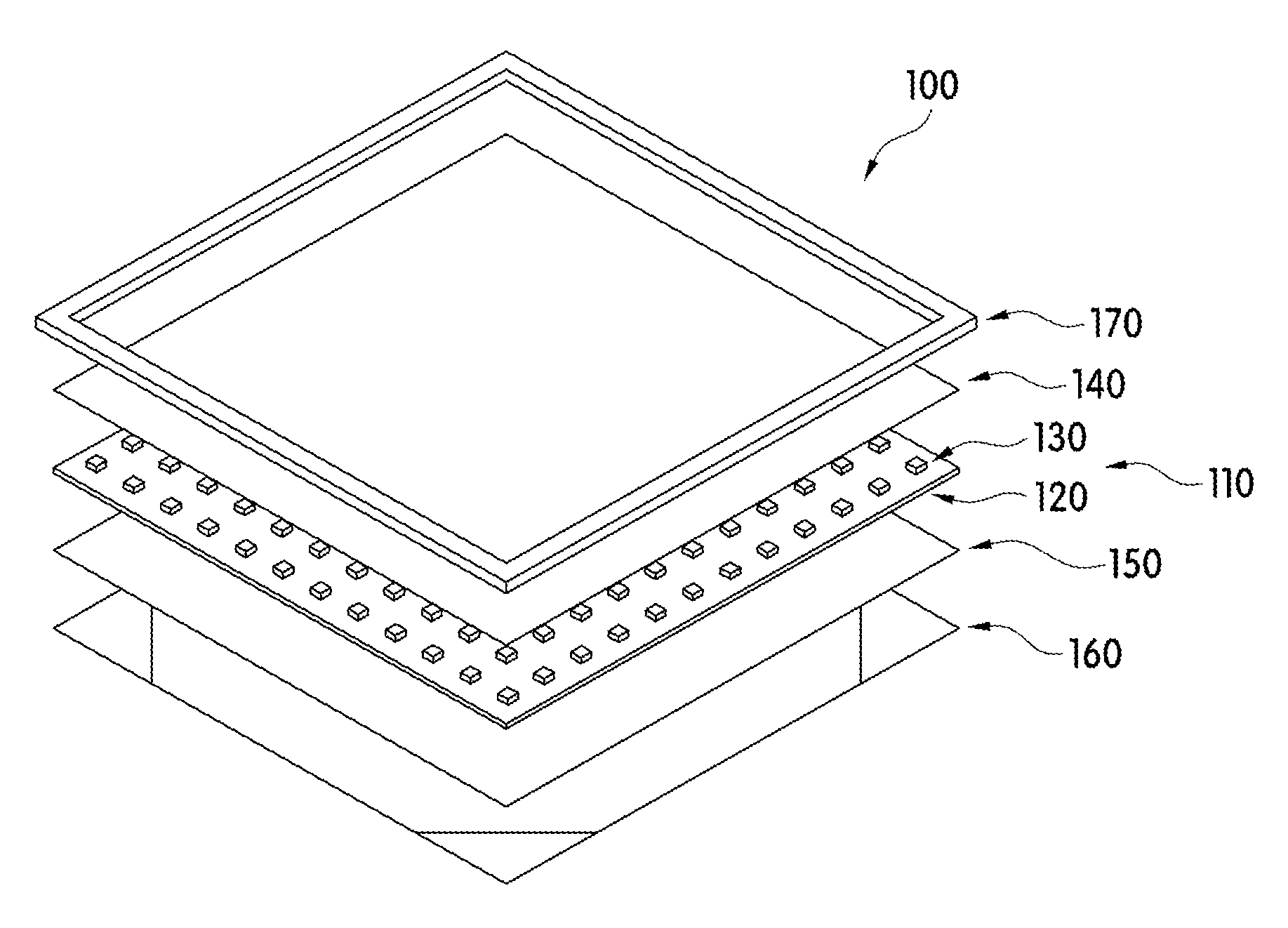
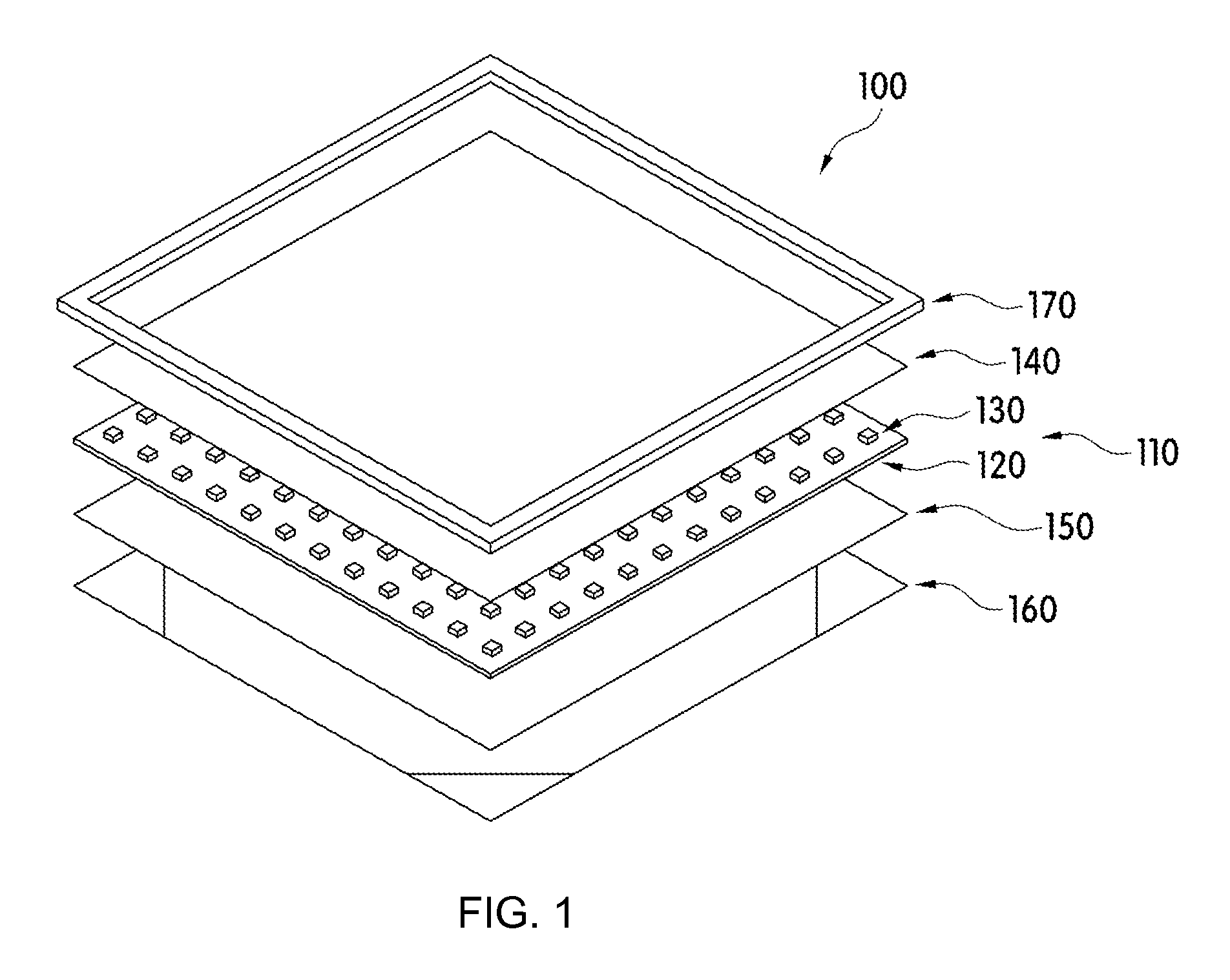
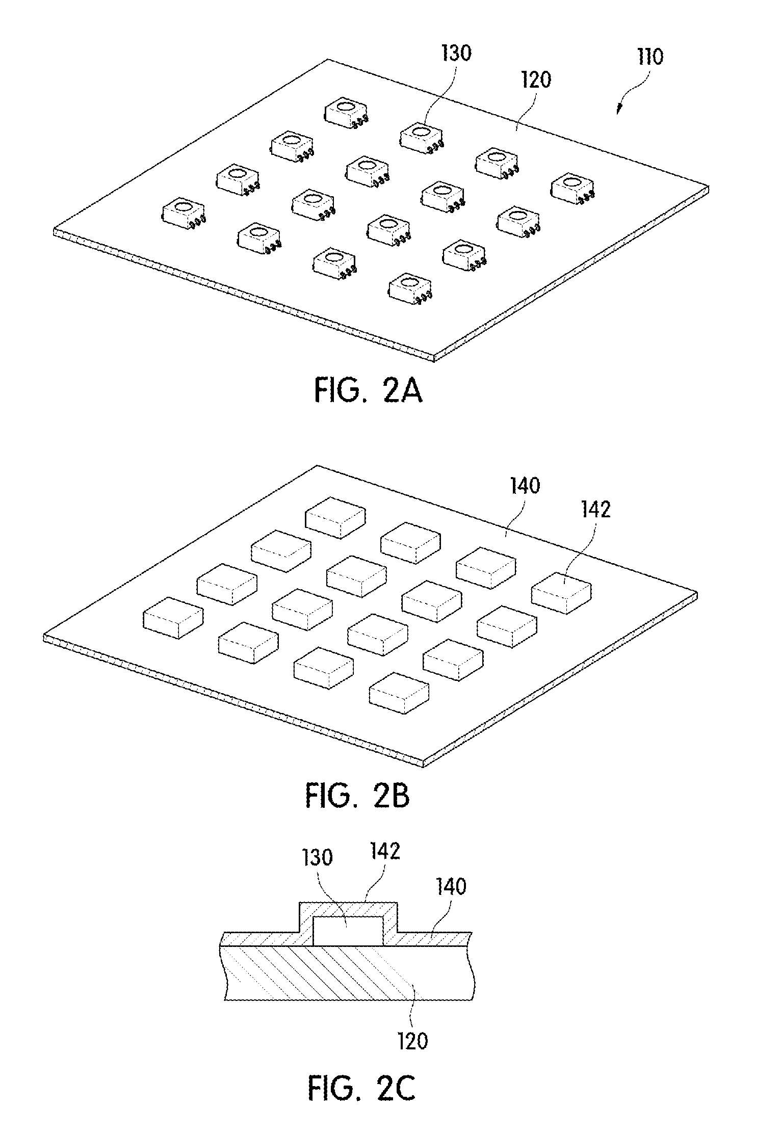
[0054]FIG. 1 is an exploded, perspective view of a flexible LED light source panel according to an embodiment of the present invention, FIG. 2A is a partial, enlarged view of a flexible LED module of the flexible LED light source panel in FIG. 1, FIG. 2B is a partial, enlarged view of a protective sheet, FIG. 2C is a cross-sectional view of when the LED module and the protective sheet are coupled, FIG. 3A is a wiring pattern diagram of the flexible circuit substrate of...


PUM


Abstract

Provided is a flexible LED light source panel including: a flexible LED module in which a plurality of LEDs is disposed in an array form on a flexible circuit board; a protective sheet stacked on the flexible LED module and diffusing light from the LEDs; a heat conduction sheet disposed under the flexible LED module; a heat radiation sheet disposed under the heat conduction sheet, made of fireproof fiber, and coated with a carbon nano tube molecule having a grid or vertical structure; and a light source guide having a quadrilateral shape.

Description

CROSS-REFERENCE TO RELATED APPLICATIONS[0001]This U.S. non-provisional patent application claims priority under 35 U.S.C. §119 of Korean Patent Application Nos. 10-2014-0040243, filed on Apr. 4, 2014, and 10-2014-0050325, filed on Apr. 25, 2014, the entire contents of which are hereby incorporated by reference.BACKGROUND OF THE INVENTION[0002]The present invention disclosed herein relates to a flexible led light source panel, and a flexible LED lighting device for capturing an image by using the same panel. In particular, the present invention relates to a flexible led light source panel that is used for taking a picture and making broadcasting and a film, and a flexible LED lighting device for capturing an image by using the same panel.[0003]In recent, a lighting device using an LED needs the feeling of color, such as cooler temperature or color rendering, unlike the past in which only the brightness of a light source has been pursued. In order to satisfy such a condition, the LED ...

Claims


Application Information

Patent Timeline
Patent Type & Authority Patents(United States)
IPC IPC(8): F21V19/00F21V14/00H01K5/00F21V23/00F21V25/12G03B15/05F21S2/00F21V29/87F21V5/00F21V21/14B82Y30/00F21W131/406F21Y105/00F21Y113/00
CPCF21V19/0035F21S2/00F21V5/006F21V14/00F21V19/003F21V21/145F21V23/008F21V25/12F21V29/87G03B15/05H01K5/00B82Y30/00F21W2131/406F21Y2101/02F21Y2105/001F21Y2113/00Y10S977/742F21Y2105/16F21Y2115/10G03B2215/0567H05K1/0206H05K2201/09072H05K2201/10106F21V11/16F21V15/00F21V23/02F21V29/83F21V29/89G03B15/06
Inventor SONG, CHANG HWANRYU, SUNG HWAN
Owner F J WESTCOTT
Learn More