
Energy-capturing floating breakwater

a technology of energy capture and floating breakwater, which is applied in the field of power generation, can solve the problems of inability to large-scale use of wave energy convertors (“wec”) currently being used in the world today, the difficulty of accurately estimating and understanding wave patterns, and the relatively slow (0.1 hz) conversion of random oscillatory motion, etc., and achieves the effect of 100% efficiency of energy capture, low viscosity, and low cos

Inactive Publication Date: 2016-08-16
MADHI FARSHAD +2
View PDF14 Cites 2 Cited by
  • Summary
  • Abstract
  • Description
  • Claims
  • Application Information

AI Technical Summary

Benefits of technology

[0016]The most preferred embodiments of the present invention comprise a one-degree-of freedom (1 DOF) ocean-wave energy capturing device with a wave-energy extraction efficiency demonstrated to be as high as 96%, with 12.5% of incident wave transmitted beyond the floating body, serving as a floating breakwater as well. Per existing inviscid-fluid theory, at the heave resonance frequency of the floating body, when the extraction damping of the PTO is matched with the radiation damping of the floating body, a 100% efficiency of energy capture and 0% of wave transmission is possible. The shape of the floating body is designed to mimic a floating body that demonstrates little viscosity effects.

Problems solved by technology

Research in this area is driven by the need to meet renewable energy targets, but is relatively immature compared to other renewable energy technologies such as solar and wind power.
However, there is no large scale use of wave energy convertors (“WEC”) currently being used in the world today.
For example, it is rather difficult to convert the relatively slow (˜0.1 Hz), random, and high-force oscillatory motion produced by a series of waves into useful motion to drive a generator with output quality acceptable to the attached utility network.
The directions of waves near the shore can be largely determined in advance owing to the natural phenomena of refraction and reflection but the difficulty associated with accurately estimating and understanding wave patterns is not a small matter.
Additionally, the challenge of efficiently capturing the relatively irregular motion associated with waves has also had an impact on the design of the device.
However, the device also has to withstand extreme wave conditions that occur very rarely, but could have power levels in excess of 2000 kW per frontal meter.
Not only does this pose difficult structural engineering challenges, but it also presents one of the economic challenges as the normal output of the device (and associated revenue) are produced by the most commonly occurring waves, yet the capital cost of the device construction is driven by a need to withstand the high power level of the extreme, yet infrequent, waves.
There are also additional design challenges that must be overcome in order to mitigate the highly corrosive environment of devices operating in or near seawater.
Finally, although many experimental and early stage wave energy extraction projects hold some promise, there yet remains a lack of convergence on the best method of extracting energy from the waves and, although previous innovation has generally focused on the concept and design of the primary interface, questions arise concerning how best to optimize the components of the systems, including the generation mechanism and the associated powertrain and energy transfer mechanisms.

Method used


Image

  • Energy-capturing floating breakwater
  • Energy-capturing floating breakwater
  • Energy-capturing floating breakwater

Examples


Embodiment Construction

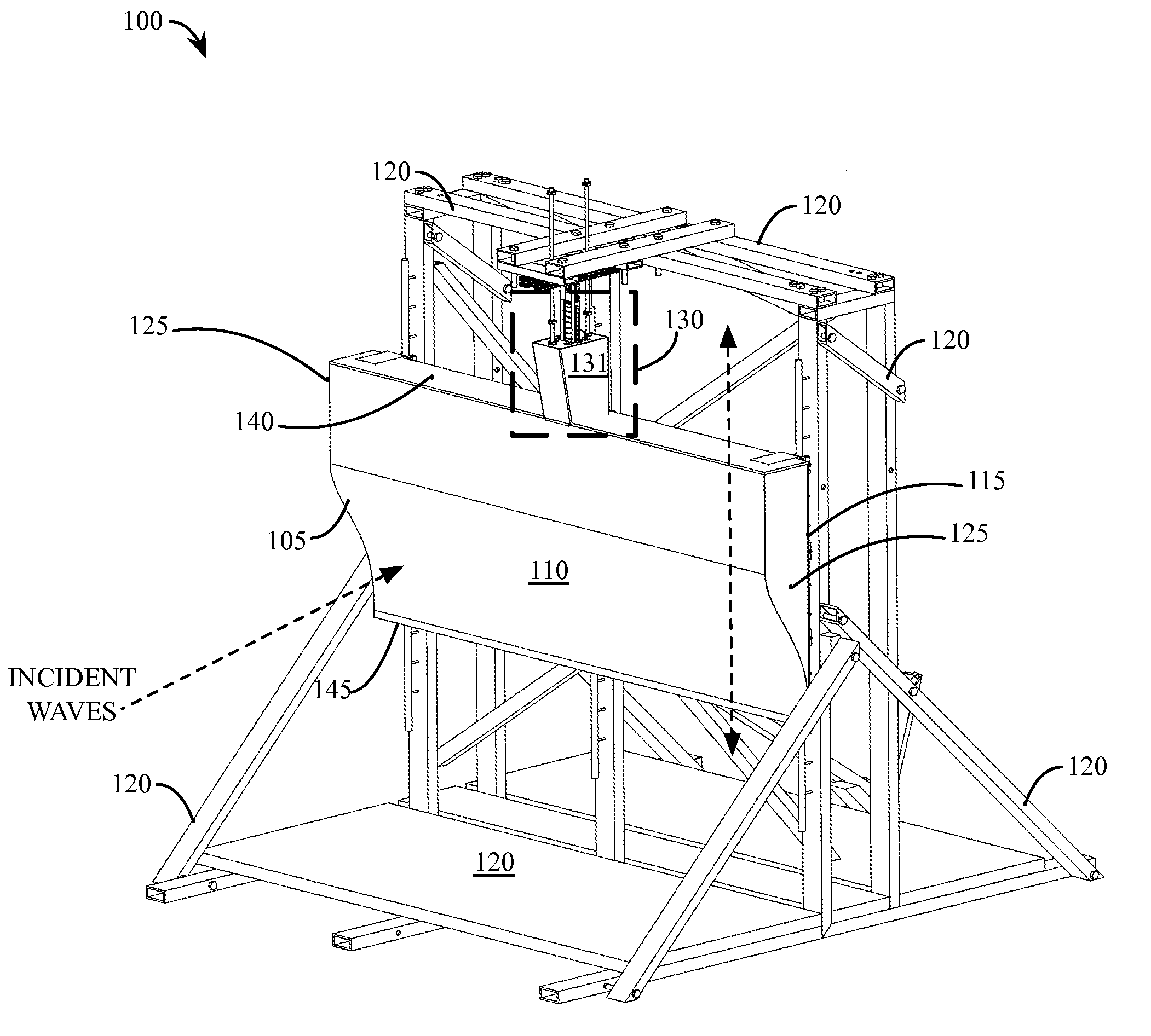
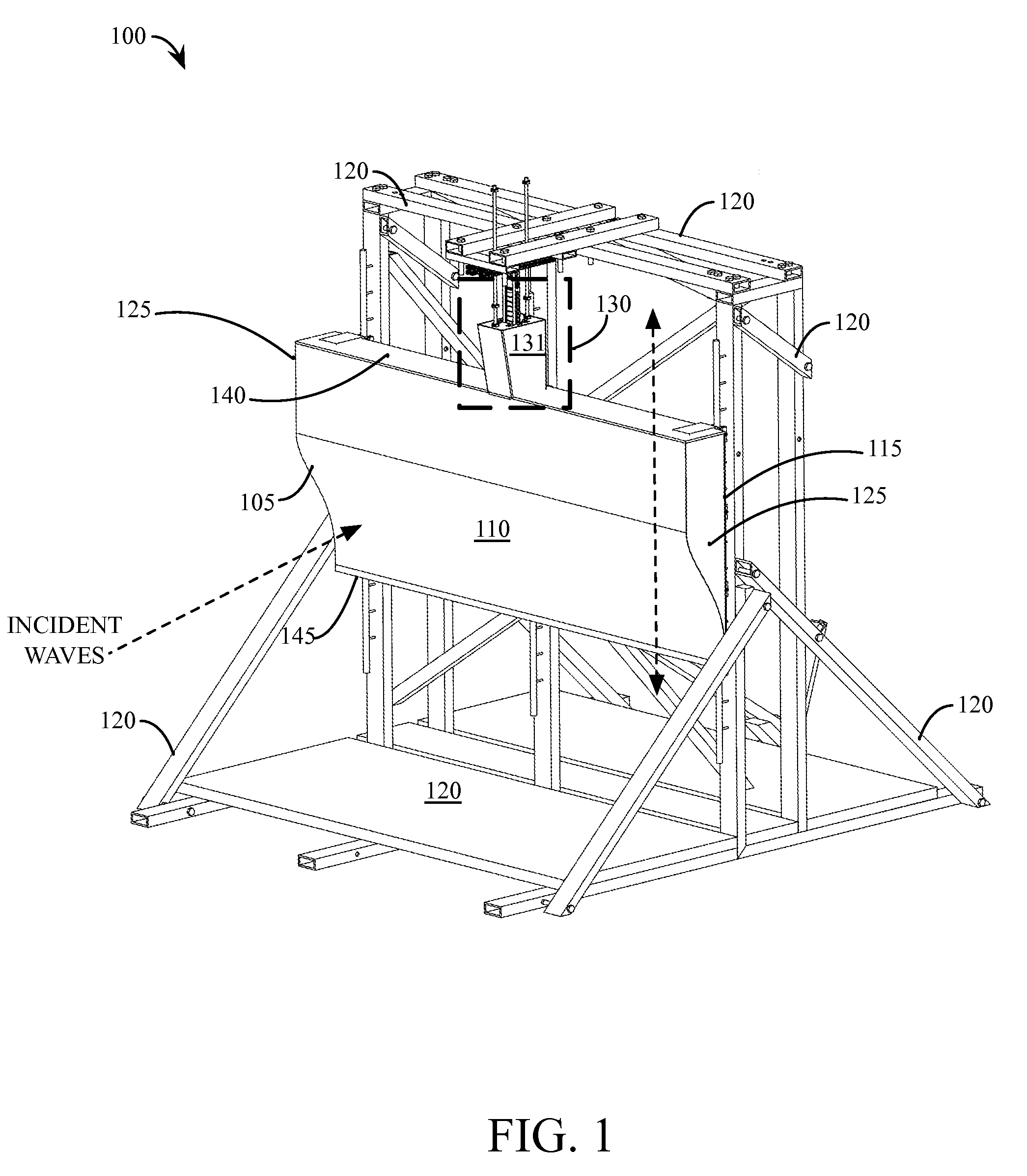
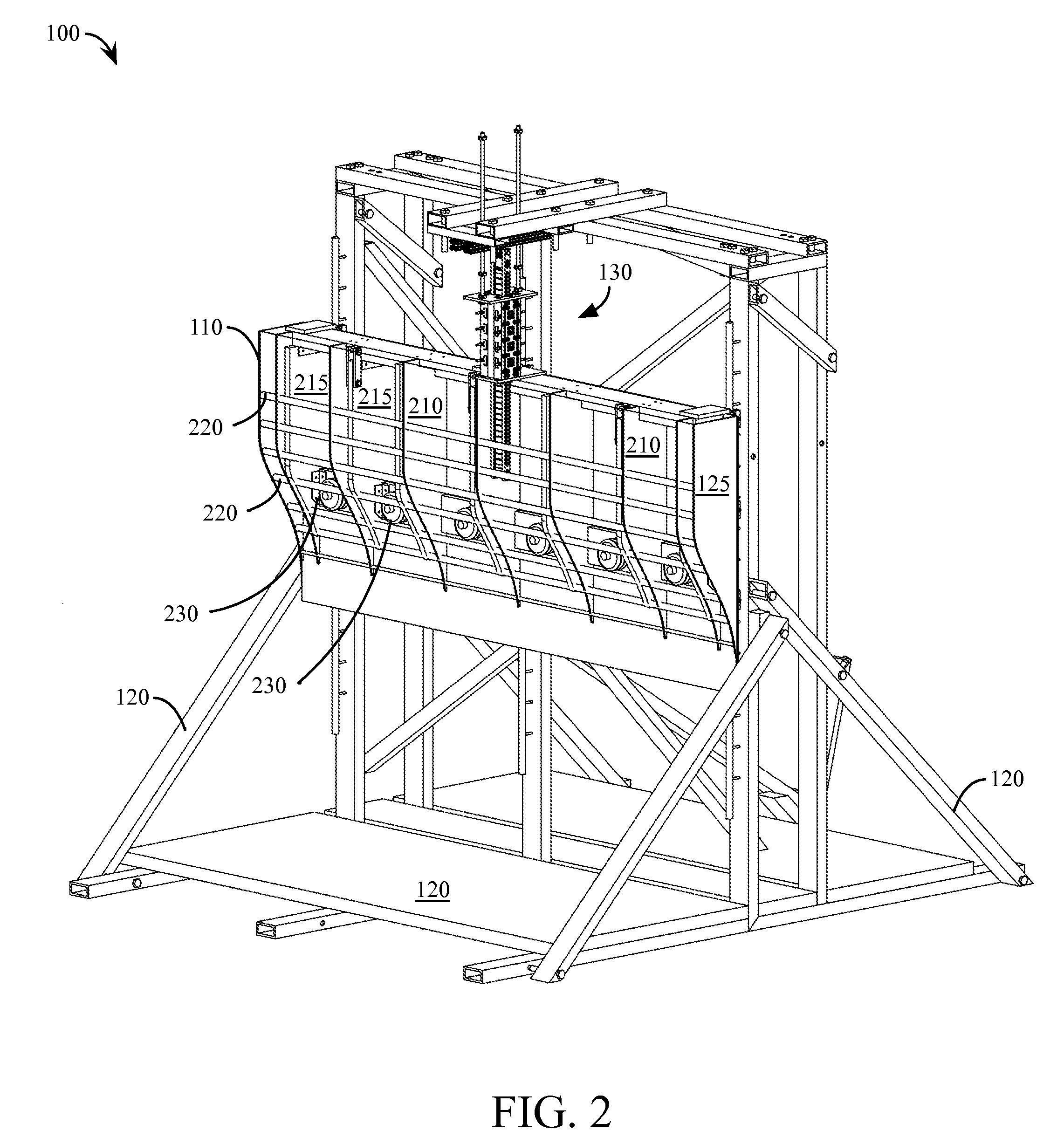
[0028]The most preferred embodiments of the present invention comprise the combination of: an asymmetrical floating body designed in accordance with the parameters in Appendix 1; a specially designed guiding structure; and a PMLG-based PTO system. With the most preferred embodiments of the present invention, the damping of the PTO is matched with the radiation damping of the asymmetrical floating body, a shape-dependent hydrodynamic property. When operated at resonance in heave motion, the most preferred embodiments of the present invention are capable of capturing up to 96% of incident-wave energy while simultaneously acting as a breakwater or wave shield, since about only 12.5% of the wave amplitude (or only 1.56% of the energy flux) will be transmitted to the leeward side.

[0029]The most preferred embodiments of the present invention are configured to capture wave energy in a broad range of frequencies. Additionally, certain preferred embodiments of the present invention may be im...


PUM


Abstract

An apparatus comprises an asymmetric heaving floating body that resists influence from viscosity effects. The asymmetric heaving floating body is coupled to a Permanent Magnet Linear Generator (“PMLG”) that serves as a power take off (“PTO”) system. A support structure for the apparatus is designed so as to restrain lateral force and pitching moment. Similarly, the asymmetric floating body is designed to minimize viscosity effects when in motion to transfer incident wave energy to the PTO.

Description

RELATED APPLICATIONS[0001]This non-provisional patent application claims the benefit of U.S. Provisional Patent Application No. 61 / 883,274, which application was filed on Sep. 27, 2014 and which application is incorporated herein by reference.BACKGROUND OF THE INVENTION[0002]1. Technical Field[0003]The present invention relates generally to the field of power generation and more specifically relates to systems and methods for creating energy from naturally occurring events and conditions.[0004]2. Background Art[0005]Ocean waves provide a significant and largely untapped potential energy resource. Research in this area is driven by the need to meet renewable energy targets, but is relatively immature compared to other renewable energy technologies such as solar and wind power. Although solar and wind power have been studied for decades, with increasingly widespread adoption, the field of wave energy conversion is still considered a relatively new area of research and development.[000...

Claims


Application Information

Patent Timeline
Patent Type & Authority Patents(United States)
IPC IPC(8): F03B13/14F03B13/18
CPCF03B13/1845F05B2220/707F05B2240/93F05B2240/97F05B2250/41Y02E10/38Y02E10/30
Inventor MADHI, FARSHADYEUNG, RONALD WSINCLAIR, MEGHAN E
Owner MADHI FARSHAD
Learn More