Method and system for ignition energy control

a technology of ignition energy and control system, applied in the direction of electric control, ignition automatic control, machines/engines, etc., can solve the problems of component durability problems, over-use of spark energy, incomplete combustion, etc., to increase the heat of vaporization, increase the charge cooling effect, and increase the octane

Active Publication Date: 2016-10-04
FORD GLOBAL TECH LLC
View PDF16 Cites 5 Cited by
  • Summary
  • Abstract
  • Description
  • Claims
  • Application Information

AI Technical Summary

Benefits of technology

[0002]Engines may be configured with direct fuel injectors that inject fuel directly into a combustion cylinder (direct injection), and / or with port fuel injectors that inject fuel into a cylinder air intake port (port fuel injection). Multi-fuel engine systems can use both port and direct injection with different fuel types provided to the different injectors. For example, direct injection of ethanol fuel may be used with port injection of gasoline fuel. Therein, the direct injection of the alcohol fuel may take advantage of the increased charge cooling effects of the alcohol fuel's higher heat of vaporization and increased octane. This helps to address knock limitations, especially under boosted conditions. Direct injection of fuel may also be used during an engine cold start to operate overall leaner than stoichiometry but richer near the spark plug for robust cylinder combustion. Further, the port injection of the gasoline fuel may take advantage of the higher energy density of the gasoline fuel and improved fuel vaporization at lower engine temperatures as compared to that of alcohol fuel.
[0006]In an alternate example, the engine system may be configured with a dual ignition coil wherein a first charging current is applied for a first dwell time on a first ignition coil, and a second charging current is applied for a second dwell time on a second ignition coil. After the first dwell time has elapsed, the first coil is discharged to the spark plug to initiate the spark event. While the first coil is discharging, and after a delay since the discharging of the first coil, the second coil is discharged to the spark plug. Herein, the dwell time for each of the first and second ignition coils may be adjusted based on the first and second fuels and based on the ratio of fuel delivery via port and direct injectors. As an example, as the amount of fuel delivered via the direct injector increases, the dwell time of the first and second ignition coils may be increased. In addition, a delay between discharging of the two coils may be decreased to. As elaborated herein, the ignition energy requirement may depend on various factors of the combustion chamber and may vary engine to engine. In general, ignition energy may be increased when the direct injection fuel fraction is higher due to increased charge and compression pressure during discharge. If the direct injected fuel fraction is split into multiple injections, e.g., an intake stroke and a compression stroke direct injection, and if the compression stroke injection is used in a stratified manner, a favorable air-fuel ratio near the spark plug may translate into a lower ignition energy requirement, as well as a lower need for a second discharging.
[0007]The adjusting of the dwell time and the delay may also be based on the fuel type delivered via the port injector and the direct injector. For example, the adjusting may be based on a difference in alcohol content of the fuels, or an octane rating of the fuels. Thus, the dwell time for each ignition coil may be lower when the port injected fuel includes gasoline and the direct injected fuel includes E85 as compared with when the port injected fuel includes gasoline and the direct injected fuel includes E10. Furthermore, the dwell time may be adjusted as a function of fuel reactivity (or ignitability). As such, higher reactivity fuels may have a lower ignition energy demand.
[0008]In this way, spark energy for a combustion event may be varied by adjusting the dwell command of an ignition coil based on cylinder fueling, the ignition energy output during a spark event in the cylinder may be better managed. In particular, the ignition energy output may better match the ignition output required for combustion of the given combination of fuels and injection types. By increasing the ignition output as fuel delivery via direct injection increases, and fuel delivery via port injection decreases, power consumption of the ignition event is improved. In addition, component durability is increased.
[0009]As such, this enables robust combustion with minimal energy usage. In addition, durability of ignition components such as ignition coils and spark plugs is not compromised.

Problems solved by technology

Managing the ignition energy output and spark duration may become even more complicated as transitions are made between fuels and injection modes.
As such, if the ignition energy output and spark duration are not adjusted to the appropriate level, various issues may occur such as incomplete combustion, over-usage of spark energy, component durability issues, fuel economy and emissions degradation.

Method used


Image

  • Method and system for ignition energy control
  • Method and system for ignition energy control
  • Method and system for ignition energy control

Examples


Embodiment Construction

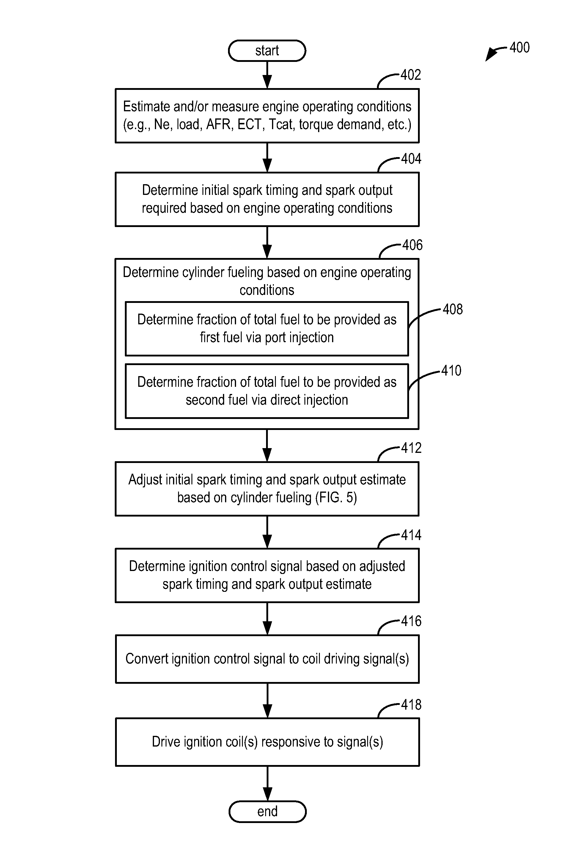
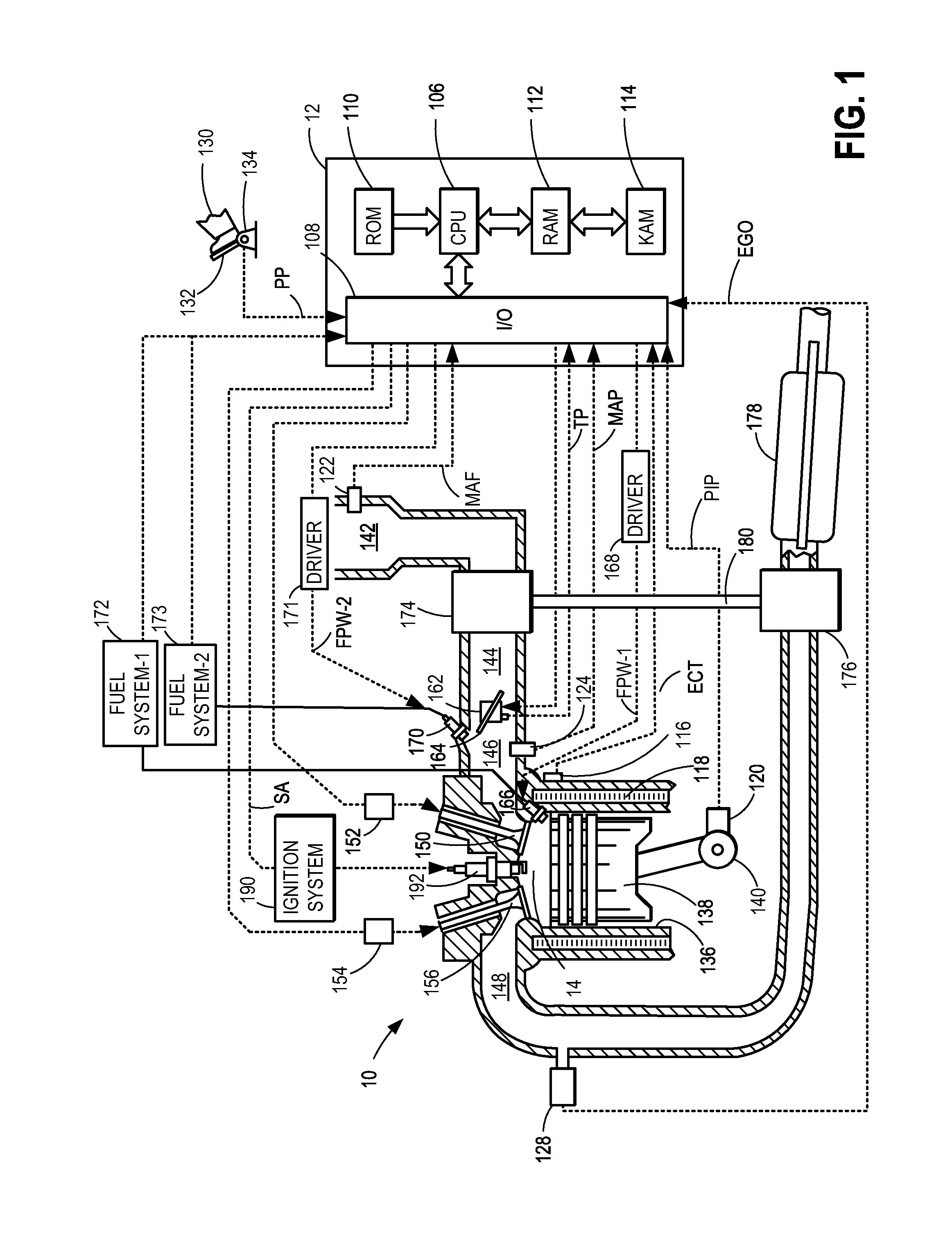
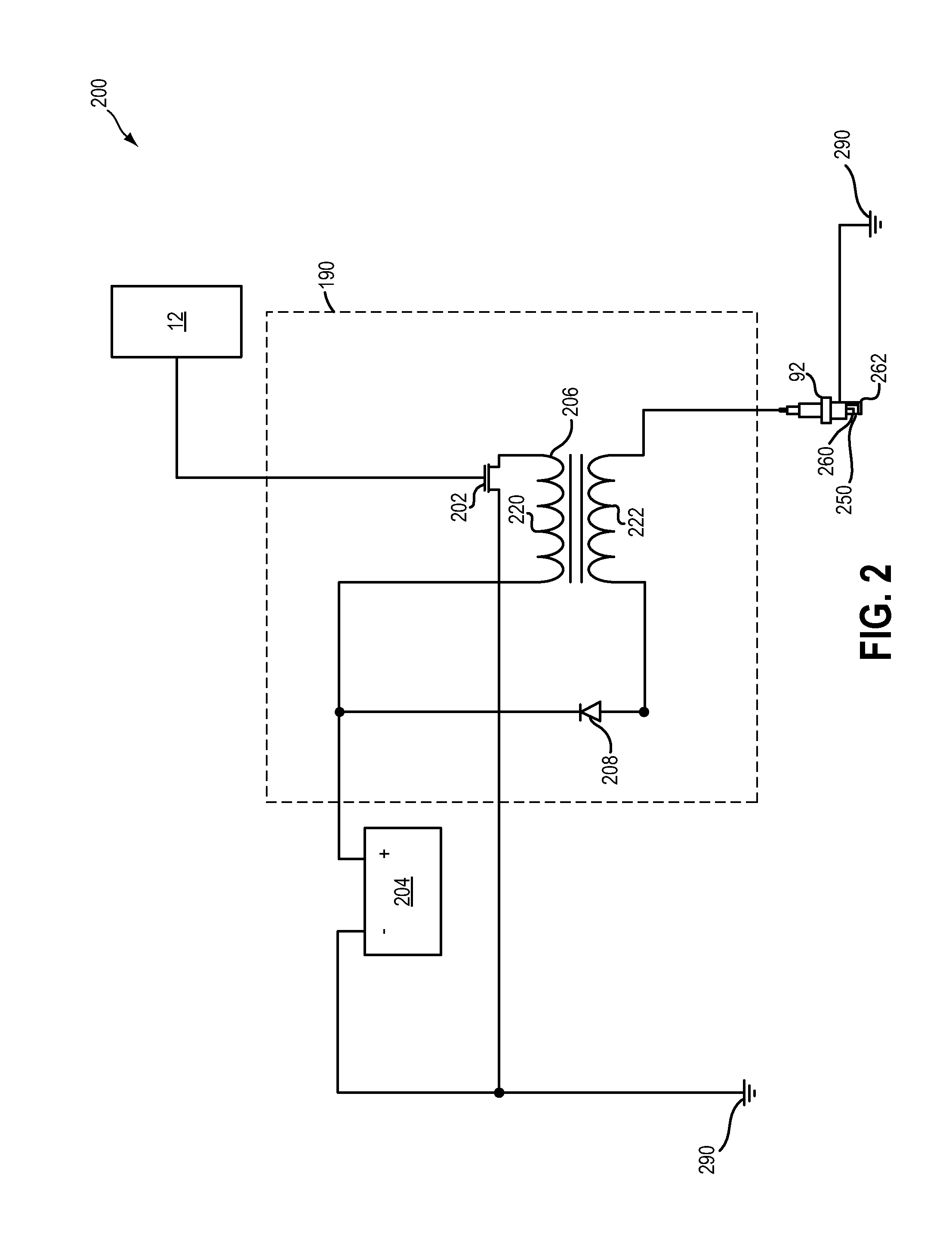
[0021]The present description is related to improved ignition energy management in a spark ignition engine, such as the engine of FIG. 1. The engine may be configured with a single coil ignition system, as described at FIG. 2, or a dual coil ignition system, as described at FIG. 3. An engine controller may be configured to perform a control routine, such as the example routine of FIGS. 4-5, to adjust an ignition coil dwell command (for either ignition system) and a delay in discharging (for dual coil ignition systems) based on cylinder fueling, including based on one or more fuels received in the cylinder and fuel injection type. The controller may accordingly adjust how long a charging current is applied as well as when the ignition coil stored energy is discharged to the spark plug on a given cylinder combustion event (FIGS. 6-7). Example trends are shown with reference to the maps of FIG. 8. An example adjustment in spark output with changing cylinder fueling is shown with refere...


PUM


Abstract

Methods and systems are provided for improving spark robustness. Spark ignition dwell commands are adjusted based on the fuel fraction delivered via direct injection relative to port injection. The approach allows ignition output to better match the ignition requirement of the given fuel combination.

Description

FIELD[0001]The present application relates to methods and systems for adjusting spark ignition energy in an engine system configured for direct and port fuel injection of fuels.BACKGROUND AND SUMMARY[0002]Engines may be configured with direct fuel injectors that inject fuel directly into a combustion cylinder (direct injection), and / or with port fuel injectors that inject fuel into a cylinder air intake port (port fuel injection). Multi-fuel engine systems can use both port and direct injection with different fuel types provided to the different injectors. For example, direct injection of ethanol fuel may be used with port injection of gasoline fuel. Therein, the direct injection of the alcohol fuel may take advantage of the increased charge cooling effects of the alcohol fuel's higher heat of vaporization and increased octane. This helps to address knock limitations, especially under boosted conditions. Direct injection of fuel may also be used during an engine cold start to operat...

Claims


Application Information

Patent Timeline
Patent Type & Authority Patents(United States)
IPC IPC(8): F02P9/00F02P3/05F02P15/00F02B17/00F02D19/08F02P3/045F02P5/04F02D41/00F02D37/02F02P5/15F02D19/06F02M25/022F02D41/30F02P7/00
CPCF02D19/084F02B17/005F02D19/061F02D19/0689F02D19/0692F02D19/081F02D37/02F02D41/0025F02P3/045F02P3/05F02P5/045F02P5/1502F02P9/002F02P15/006F02D19/0694F02D41/3094F02M25/0228F02P7/00Y02T10/36Y02T10/46F02P9/007F02P3/0407Y02T10/30Y02T10/40
Inventor GLUGLA, CHRIS PAULHUBERTS, GARLAN J.
Owner FORD GLOBAL TECH LLC
Why Eureka
Try Eureka