Seismic geophysical surveying

a geophysical surveying and seismic technology, applied in seismology, geological measurements, instruments, etc., can solve the problems of changing environmental conditions, high cost of geophone arrays, and limited number of individual sensing elements in arrays, and achieve the effect of narrow pulse widths

Active Publication Date: 2016-10-11
OPTASENSE HLDG LTD
View PDF8 Cites 15 Cited by
  • Summary
  • Abstract
  • Description
  • Claims
  • Application Information

AI Technical Summary

Benefits of technology

[0036]Advantageously the interrogating electromagnetic radiation comprises a pulse pair comprising a first pulse followed by, and temporally separated from, a second pulse. A pulse structure that has relatively narrow pulse widths compared to the gap between pulses can be advantageous in terms of allowing diversity samples to be acquired within the maximum achievable spatial resolution of the sensor. The duration between the first and second pulses may therefore be equal to or greater than the pulse duration of the first pulse and / or second pulse and may be at least twice the pulse duration of the first pulse and / or second pulse.

Problems solved by technology

Firstly geophone arrays are expensive and thus are typically deployed for an individual survey and then recovered after the survey for use at another location.
Also the expense of geophone arrays means that the number of individual sensing elements in an array is typically limited.
The results from the different sections may then be stitched together but there can be problems in accurately aligning the positions of the geophones at different depths and also, in the time taken to relocate the geophone array, the environmental conditions may have changed.
Further, for a production well inserting a geophone array would require a well intervention which temporarily halts production.

Method used


Image

  • Seismic geophysical surveying
  • Seismic geophysical surveying
  • Seismic geophysical surveying

Examples


Embodiment Construction

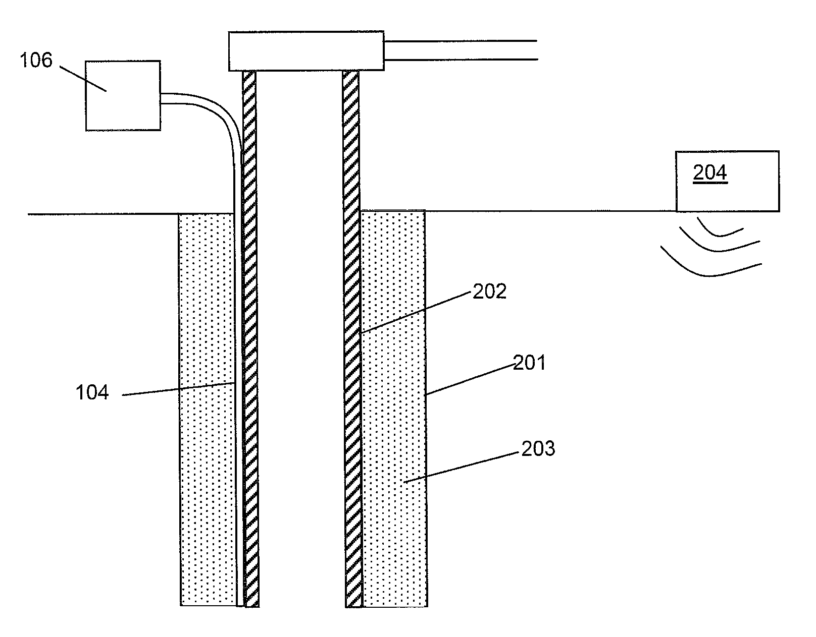
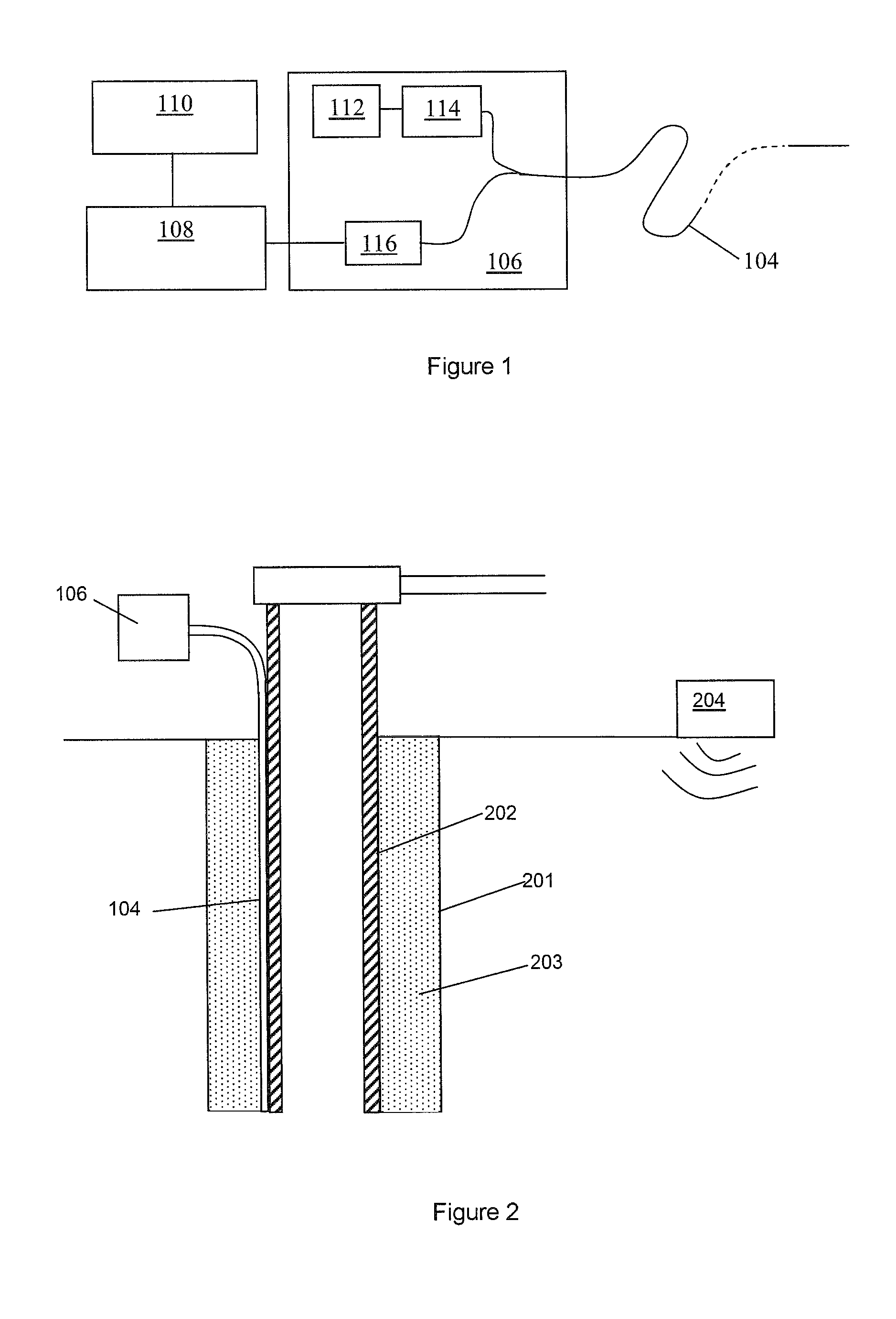
[0053]FIG. 1 shows a schematic of a distributed fibre optic sensing arrangement. A length of sensing fibre 104 is removably connected at one end to an interrogator 106. The output from interrogator 106 is passed to a signal processor 108, which may be co-located with the interrogator or may be remote therefrom, and optionally a user interface / graphical display 110, which in practice may be realised by an appropriately specified PC. The user interface may be co-located with the signal processor or may be remote therefrom.

[0054]The sensing fibre 104 can be many kilometers in length and may, for example, be at least as long as the depth of a wellbore which may be at least 1.5 km long. The sensing fibre may be a standard, unmodified single mode optic fibre such as is routinely used in telecommunications applications without the need for deliberately introduced reflection sites such a fibre Bragg grating or the like. The ability to use an unmodified length of standard optical fibre to pr...


PUM


Abstract

The present invention relates to an apparatus for use in geophysical surveying. Geophysical surveying typically involves stimulating an area of interest with a seismic source (204) and detecting the response in a sensor array. The application describes a fiber optic distributed sensing apparatus having a source (112) of electromagnetic radiation for repeatedly launching interrogating electromagnetic radiation into an optic fiber (104) deployed in said of area interest, a sampling detector (116) for sampling radiation back-scattered from the fiber; and a processor (108) arranged to process the back-scattered radiation to provide, for each of a plurality of longitudinal sensing portions of optic fiber, an indication of any incident acoustic signals affecting that sensing portion. The sampling detector is arranged to acquire a plurality of diversity samples for each said longitudinal sensing portion. The processor is configured process the diversity samples in diversity channels to determine a measurement signal indicative of any acoustic disturbance; correlate the measurement signal from each channel with a signal indicative of the seismic stimulus applied; and combine the correlated measurement signals to provide an overall measurement signal for the longitudinal sensing portion. The processor may apply a quality metric to the correlated data before performing the combination based on the quality metric. By correlating the individual diversity channels with the stimulus signal prior to performing the analysis of the measurement signal for a particular longitudinal section of optic fiber, the signal to noise ratio can be improved.

Description

FIELD OF THE INVENTION[0001]The present invention relates to seismic geophysical surveying using fibre optic distributed acoustic sensors and in particular to improved methods and apparatus for seismic geophysical surveying, for example vertical seismic profiling, in wellbores.BACKGROUND OF THE INVENTION[0002]Seismic geophysical surveying is used in a variety of applications. For example in the oil and gas sector seismic surveys may be conducted at numerous different stages of well construction and operation. In particular, once well construction has been completed and the wells are operational there may be a desire to perform periodic seismic surveys in order to highlight any significant changes in the condition of the wells and / or the reservoir over time.[0003]Seismic surveys may also be used for assessing reservoirs for the storage of hazardous or unwanted materials, for example in carbon dioxide sequestrations schemes. In these applications there may again be a desire to underta...

Claims


Application Information

Patent Timeline
Patent Type & Authority Patents(United States)
IPC IPC(8): G01V1/36G01V1/22
CPCG01V1/366G01V1/226G01V1/02G01V1/22G01V8/00
Inventor LEWIS, ANDREWRUSSELL, STUART
Owner OPTASENSE HLDG LTD
Why Eureka
Try Eureka