ANSI reference ballast compliance circuit for LED retrofit lamps

a technology of retrofit lamps and ballasts, applied in the direction of semiconductor lamps, light sources, lighting and heating apparatus, etc., can solve the problems of traditional lamp circuits, prior art technology does not disclose the design circuit, and cannot teach the maintenance of retrofit compatibility, so as to maximize the compatibility and efficient replacement

Active Publication Date: 2016-10-11
SIGNIFY HLDG BV
View PDF21 Cites 13 Cited by
  • Summary
  • Abstract
  • Description
  • Claims
  • Application Information

AI Technical Summary

Benefits of technology

[0012]The present invention provides an LED retrofit lamp that efficiently replaces HID or fluorescent lamps by maximizing their compatibility with the ballasts available in the market.
[0016]It is further an objective of the present invention to provide a retrofit LED lamp that consumes less power, without compromising with the efficiency.
[0017]It is also an objective of the present invention to provide an LED lamp that has maximum compatibility with the large installed base of ballasts in the market.
[0019]Furthermore, an embodiment of the present invention provides an LED lamp to be driven by a dual mode circuit, where the dual mode circuit comprises a thevenin equivalent circuit used as an equivalent for traditional cathode heaters used in fluorescent lamps. The operating ballast with the LED lamps provides a constant voltage to the one or more LEDs of the lamp via the thevenin equivalent circuit, which provides impedance to the lamp. The dual mode circuit further comprises capacitors that couple the LEDs with the ballast, where the capacitors are not small enough to offer material reactive impedance but also allows changing the reference lamp to a single ended structure and only using a single FET to latch the lamp on or off.
[0020]Another embodiment of the present invention provides the dual mode circuit including an RC filter (resistor-capacitor circuit) and a comparator (U1A) connected across the LEDs. During the ballast testing mode, due to insufficient current, the RC filter and the comparator are not conducting, causing the FET to be in open circuit; and the current is passed via the bypass capacitor to the LEDs. LEDs of the lamp in this mode operate but at a very low power. This is referred to as “pre-latch” mode. Sufficient impedance is presented to the lamp by the thevenin circuit and the coupling capacitors; this allows the ANSI ballast tester to pass the testing mode.

Problems solved by technology

The prior art technologies fail to disclose the design circuits for the LED lamps that are satisfying the operational characteristics as per UL ANSI standards.
Further, none of the prior art technologies teach about maintaining the compatibility of the retrofit LED lamps with the ballasts present in the market to replace fluorescent or HID lamps.
Furthermore, there are several problems with traditional lamp circuits.
Similarly, power consumption is more in the traditional lamps.
Also, when a traditional approach of adding a capacitive coupling between the retrofit lamp and ballast to add a reactive component to the lamp impedance and throttle back current is implemented, the approach does not work during compatibility testing for two reasons: the difference in power level that a compatible compact florescent lamp (“CFL”) LED lamp is seeking to bridge (50%) is larger than what is typically bridged in HID or linear fluorescent or other lamps (20-30%).
This larger reactance creates compatibility issues with ballasts that operation at lower frequencies and its impedance is higher and thus causes the ballast to turn off after hitting its over voltage protection limit or other protection circuitry.
Therefore, high compatibility cannot be achieved with a simple reactive circuit.

Method used


Image

  • ANSI reference ballast compliance circuit for LED retrofit lamps
  • ANSI reference ballast compliance circuit for LED retrofit lamps
  • ANSI reference ballast compliance circuit for LED retrofit lamps

Examples


Embodiment Construction

[0026]In the following detailed description of embodiments of the invention, numerous specific details are set forth in order to provide a thorough understanding of the embodiment of invention. However, it will be obvious to a person skilled in art that the embodiments of the invention may be practiced with or without these specific details. In other instances well known methods, procedures and components have not been described in detail so as not to unnecessarily obscure aspects of the embodiments of the invention.

[0027]Furthermore, it will be clear that the invention is not limited to these embodiments only. Numerous modifications, changes, variations, substitutions and equivalents will be apparent to those skilled in the art, without parting from the spirit and scope of the invention.

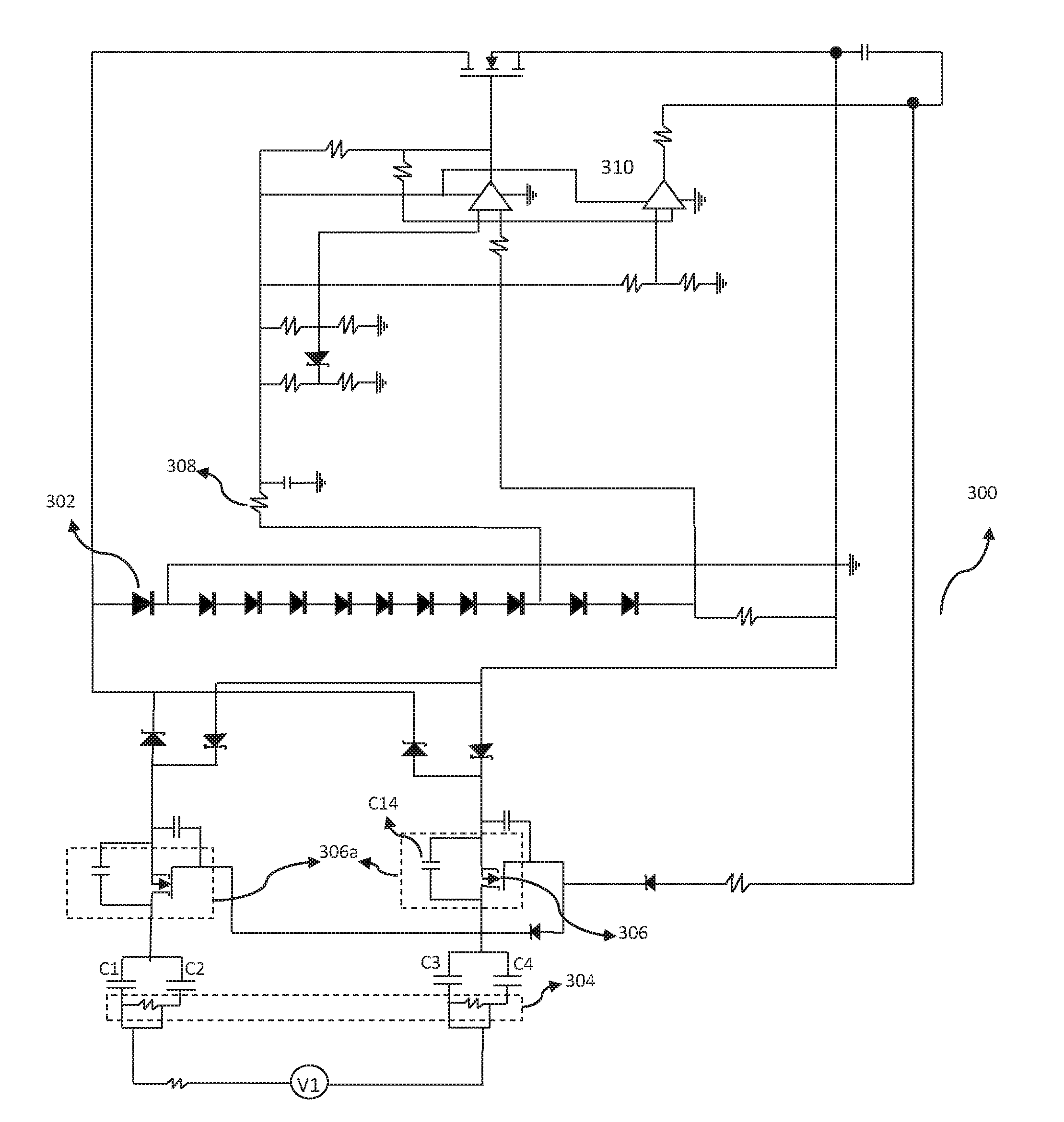
[0028]The present invention provides an LED lamp operating through a dual mode electrical circuit 300 that enables the LED lamp to have maximum compatibility with the UL ANSI ballasts available in t...


PUM


Abstract

An embodiment of the present invention provides a retrofit LED lamp that is operated by a dual mode circuit, enabling maximum compatibility with the ANSI reference ballasts to satisfy UL requirements to replace HID and fluorescent lamps. The LED lamp operates at two different modes, offered by the dual mode PCB circuit. In one of the mode, namely ANSI ballast testing, a low frequency current from the ballast is throttled through a bypass circuit to LEDs, since a field effect transistor of the circuit is in open circuit mode due to insufficient current. During the second mode, namely field ballast operation, a high frequency current is provided by the ballast, which short circuits the FET, causing it to conduct and thus operating the LEDs. Advantageously, the LED lamp offers maximum compatibility with ballasts using such dual mode circuit and consumes less power.

Description

FIELD OF THE INVENTION[0001]The present invention relates to the field of illumination using fluorescent and light-emitting diode (“LED”) lamps. More particularly, the invention relates to an electric circuit for the operation of the lamps to increase their compatibility with the ballasts present in the market.BACKGROUND[0002]A lamp is an energy converter. Although it may carry out secondary functions, its prime purpose is the transformation of electrical energy into visible electromagnetic radiation. There are various types of lamps that are available in the market namely incandescent lamp, high intensity discharge lamp, tungsten halogen lamps, tubular fluorescent lamps, compact fluorescent lamps, induction lamps, mercury lamps, metal halide lamps, sodium lamps and many more.[0003]A fluorescent lamp or a fluorescent tube is a low pressure mercury-vapor gas-discharge lamp that uses fluorescence to produce visible light. High-intensity discharge lamps (HID lamps) are a type of electr...

Claims


Application Information

Patent Timeline
Patent Type & Authority Patents(United States)
IPC IPC(8): H05B33/08F21K99/00H05B44/00
CPCH05B33/083F21K9/27H05B33/0812H05B33/0815H05B33/0887H05B45/44Y02B20/30
Inventor BARNETSON, DONCHEIM, DARYLKIRMEIER, JOSEFWANG, BEN
Owner SIGNIFY HLDG BV
Why Eureka
Try Eureka