Regenerative braking system for reducing fuel consumption

Active Publication Date: 2016-11-01
CATERPILLAR INC
View PDF4 Cites 4 Cited by
  • Summary
  • Abstract
  • Description
  • Claims
  • Application Information

AI Technical Summary

Benefits of technology

The present patent relates to a method for reducing fuel consumption of a machine during regenerative braking. This is achieved by directing at least part of the regenerated power from the traction motor to the generator through an inverter during the regenerative braking mode. The inverter is electrically connected in parallel with the rectifier and the electrical output of the inverter is directed through a filter to remove transient voltage. The technical effect of this method is to provide a more efficient use of regenerated power, resulting in reduced fuel consumption and lower operational costs for the machine.

Problems solved by technology

Meanwhile, the engine still needs to consume fuel to power all parasitic loads and / or auxiliary devices during regenerative braking or idling of the mobile machine.
Thus, in this way, the regenerated electrical energy is wasted without reducing any fuel consumption of the engine.
A drawback of this arrangement is that the usually heavy energy storage devices add extra weight to the mobile machine and may increase fuel consumption in the traction mode.
However, because the rectifiers only allow power flowing in a single direction, i.e., from AC to DC, additional power conversion units are needed to reversely communicate the regenerated electrical energy to the generator.
Although the drive system of the '480 patent may provide an electrical pathway for using the regenerated electrical energy to power the engine, the system may lack electrical stability.
In particular, the parallel-connected additional inverter can generate fast-changing transient voltage that may turn on the diodes in the rectifier, causing erroneous current circulation.
Such current circulation not only causes power loss, but also leads to current distortion disturbing other sensitive loads and equipment in the drive system.
In serious cases, the current distortion may cause voltage spikes, circuit overheating, damages to control system, etc.
Moreover, the transient voltage may cause high voltage buildup at the slow-responding diodes of the rectifier.
This high voltage may generate electrical arc that damages the diodes and / or the contactor.

Method used


Image

  • Regenerative braking system for reducing fuel consumption
  • Regenerative braking system for reducing fuel consumption
  • Regenerative braking system for reducing fuel consumption

Examples


Embodiment Construction

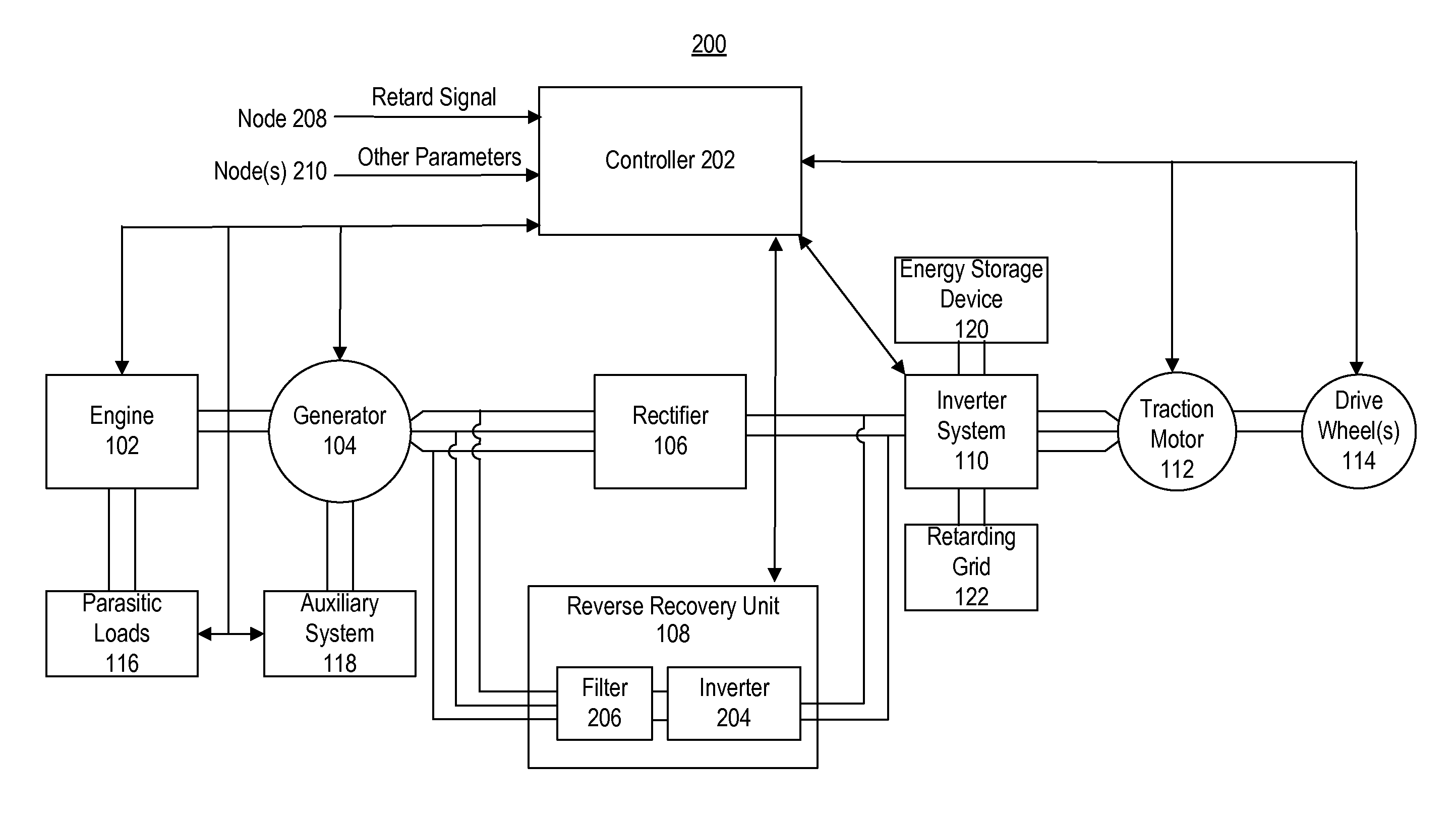
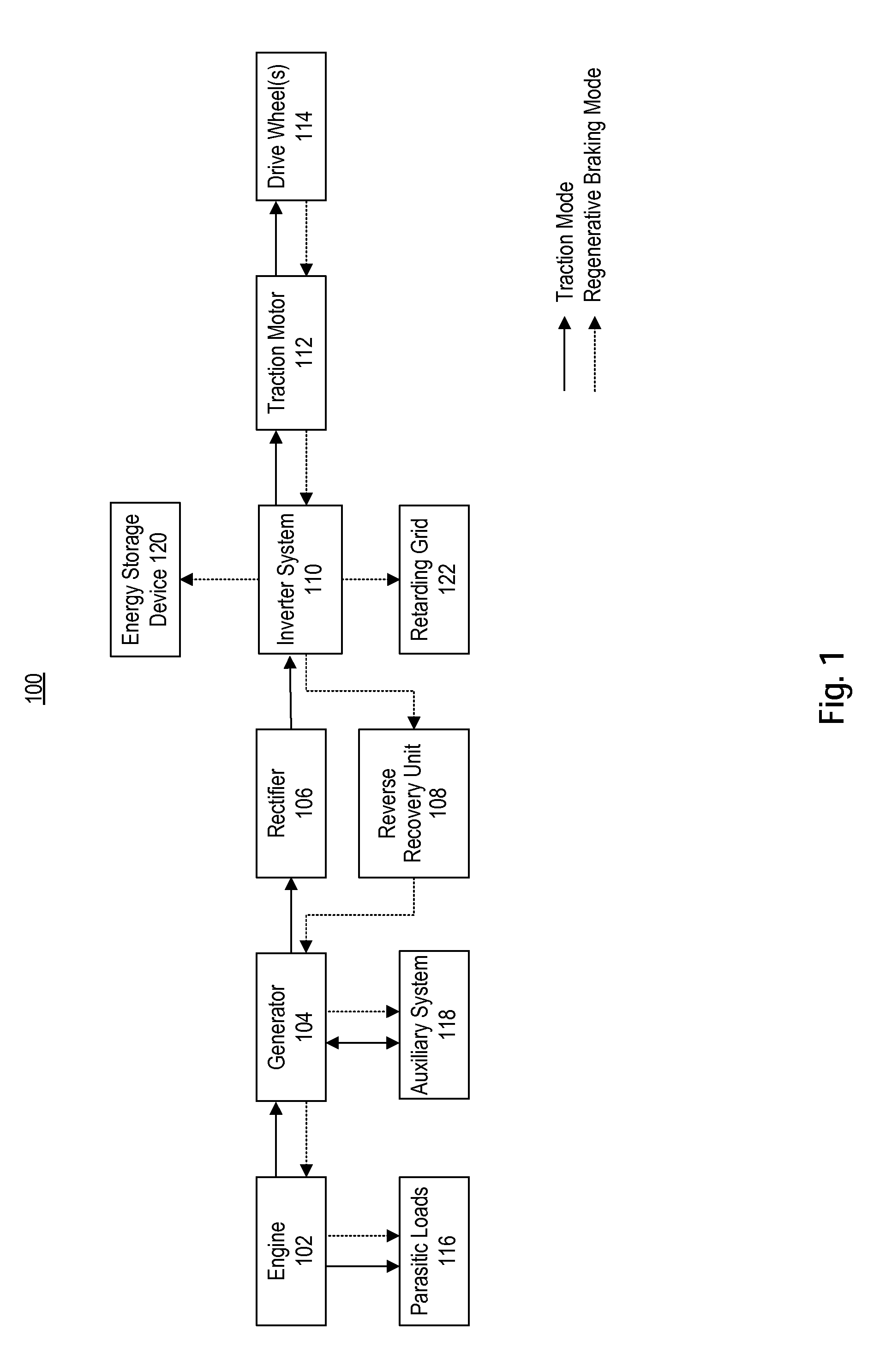
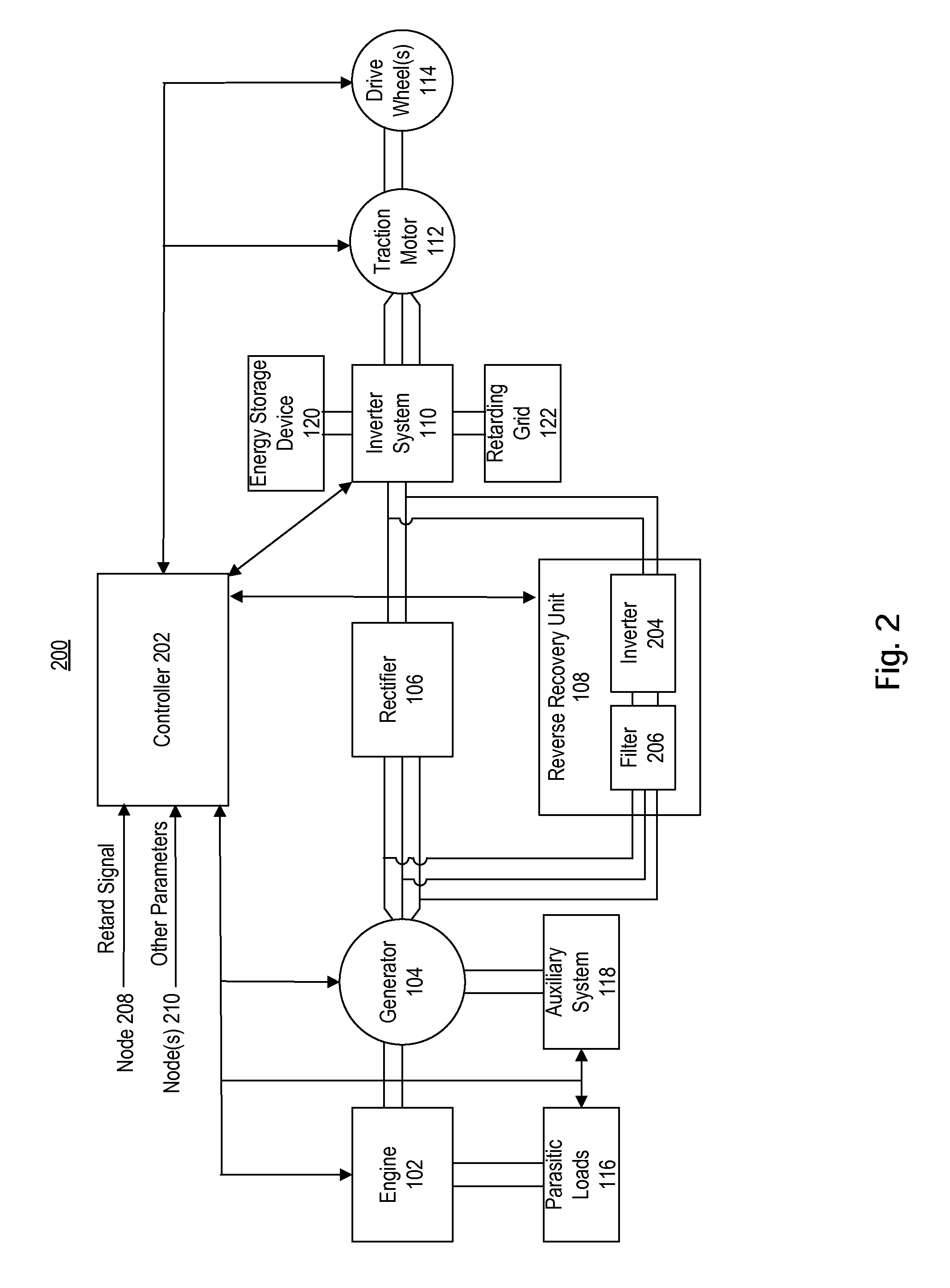
[0016]FIG. 1 schematically illustrates a mobile machine 100 including a regenerative braking system for reducing fuel consumption. The mobile machine 100 may include an engine 102, a generator 104, a rectifier 106, a reverse recovery unit 108, an inverter system 110, a traction motor 112, one or more drive wheels 114, parasitic loads 116, an auxiliary system 118, an energy storage device 120, a retarding grid 122.

[0017]Engine 102 may be an internal combustion engine and serve as the primary power source of machine 100. Engine 102 may be configured to provide direct or indirect power to parasitic loads 116 via belts, hydraulic systems, and the like. Engine 102 may also be mechanically coupled to generator 104 through a drivetrain that may include, for example, a crankshaft, a torque converter, a transmission, clutches, gears, and other drivetrain components. Generator 104 may be electrically connected to auxiliary system 118. Auxiliary system 118 may include one or more auxiliary dev...


PUM


Abstract

Systems and methods are disclosed for reducing engine fuel consumption during regenerative braking. According to certain embodiments, the regenerative braking system has an engine, a generator, a rectifier, a first inverter, a traction motor, and a reverse recovery unit. The generator is configured to be driven by the engine to produce AC electrical power. The rectifier is configured to receive AC electrical power from the generator and convert the AC power to DC power. The first inverter is configured to receive the DC power and convert the DC power to AC power. The traction motor is configured to be driven by the AC power in a traction mode, and to produce regenerated power when rotated in reverse in a regenerative braking mode. The reverse recovery unit has a second inverter and a filter. The second inverter is electrically connected in parallel with the rectifier and configured to communicate at least part of the regenerated power from the traction motor to the generator during the regenerative braking mode. The filter is electrically connected downstream of the second inverter and in parallel with the rectifier. The filter is configured to filter transient voltage generated by the second inverter during the regenerative braking mode.

Description

TECHNICAL FIELD[0001]The present disclosure relates generally to a regenerative braking system, and more particularly, to a regenerative braking system for reducing fuel consumption by an engine.BACKGROUND[0002]A typical electric drive system for a mobile machine, such as a mining truck, includes a prime mover to produce a mechanical output received by a generator. For example, the prime mover may be an internal combustion engine and the mechanical output may be a rotation of a crankshaft. The generator is driven by the mechanical output to produce an alternating current (AC) output. A first set of power electronics, such as rectifiers, may receive the AC output and convert the AC to a direct current (DC) output. The DC output is then passed through a second set of power electronics, such as inverters that convert the DC output to an AC output with a desired frequency. When the mobile machine is operating in a traction mode, this AC output is then used to drive one or more traction ...

Claims


Application Information

Patent Timeline
IPC IPC(8): H02P3/14B60L7/06B60L7/20H02P27/04
CPCB60L7/20H02P3/14H02P27/04B60L7/06B60L7/14B60L15/007B60L15/2009B60L2210/30B60L2210/40B60L50/61H02P27/06Y02T10/62Y02T10/64Y02T10/70Y02T10/72Y02T90/16Y02T10/7072
Inventor SI, BAOJUNSELVEY, DUSTIN C.TATE, WILLIAM J.TRUMPER, MARY JILLCROSMAN, III, ALEXANDER CAMERON
Owner CATERPILLAR INC
Why Eureka
Try Eureka