Reinforced wiper element

Active Publication Date: 2016-11-01
NV BEKAERT SA
View PDF19 Cites 1 Cited by
  • Summary
  • Abstract
  • Description
  • Claims
  • Application Information

AI Technical Summary

Benefits of technology

[0012]It is an object of the present invention to provide a wiper blade reinforced with at least one reinf

Problems solved by technology

In addition, the reinforcement elements have limited flexibility in a direction transverse thereto to provide some rigidity for the wiper element as it is driven back and forth across the glass.
However, galvanise

Method used


Image

  • Reinforced wiper element
  • Reinforced wiper element

Examples


Example

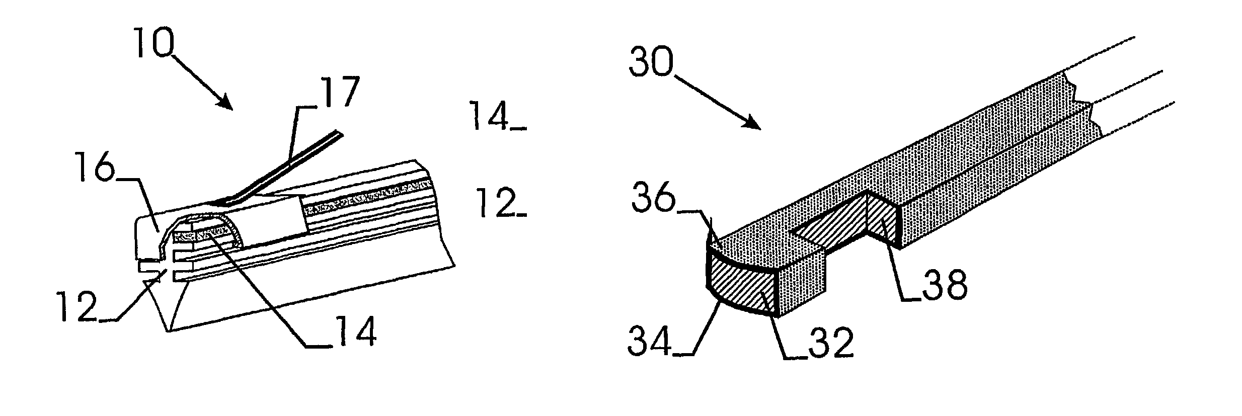
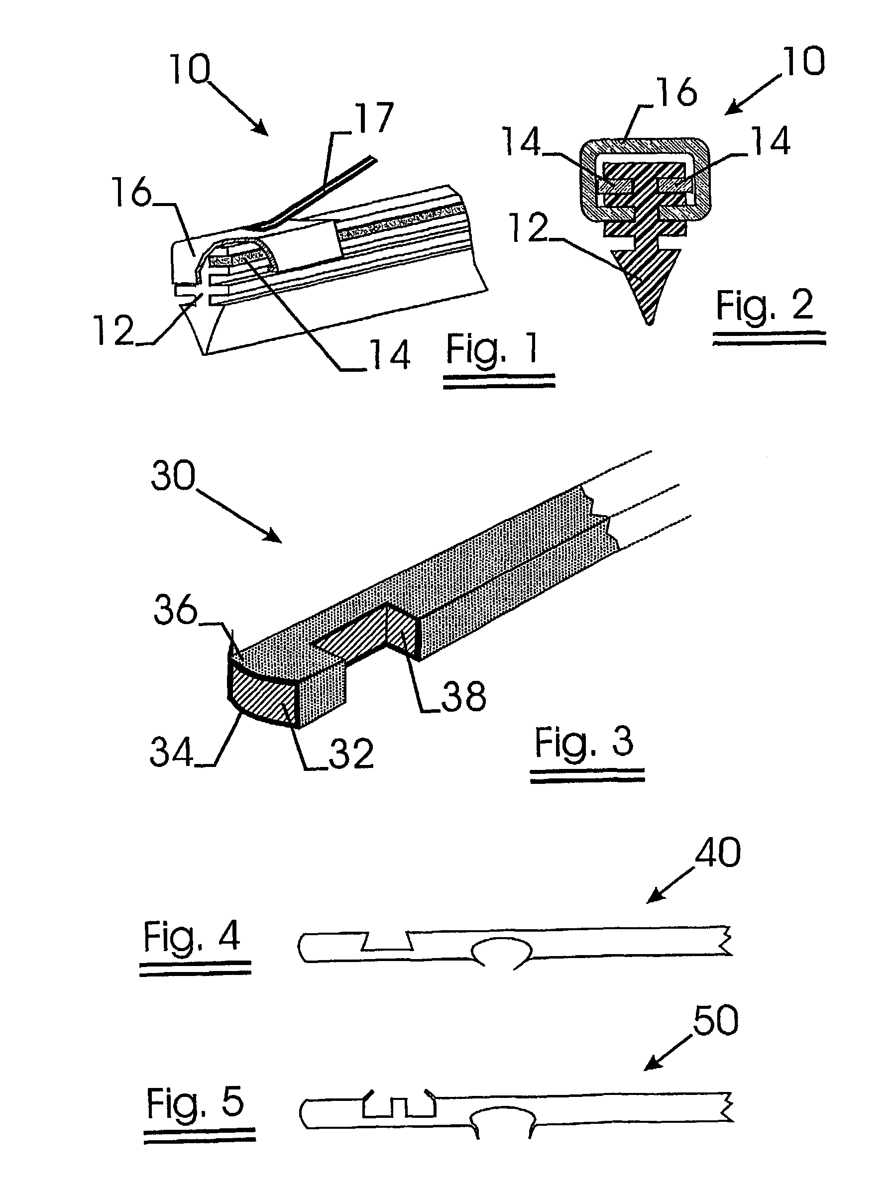
[0086]FIG. 1 shows a perspective view of a part of a windshield wiper element 10 according to the invention. FIG. 2 is a cross-sectional view of the wiper element shown in FIG. 1.

[0087]The wiper blade 12 is made of rubber and is reinforced with two reinforcement elements 14 inserted in two longitudinally extending recesses provided in the wiper blade.

[0088]The reinforcement elements stiffen the rubber wiper blade while allowing it to be flexible enough so that it can conform to the surface of a curved windshield.

[0089]An anchoring claw 16, fixed on a frame 17, partially surrounds the upper portion of the wiper blade. The claw is thereby positioned in a pair of notches. It compresses the reinforcement elements towards each other on the wiper blade and immobilises them.

[0090]Other embodiments of wiper blades are reinforced by only one reinforcement element located in a longitudinally extending recess centrally provided in the wiper blade.

[0091]Possibly, such a reinforcement element is...


PUM

PropertyMeasurementUnit
Fractionaaaaaaaaaa
Fractionaaaaaaaaaa
Fractionaaaaaaaaaa

Abstract

The invention relates to a wiper element comprising a wiper blade made of an elastomeric material and reinforced with at least one elongated element (30). The elongated element (30) comprises a core (32) and a coating system (36). The coating system comprises a zinc alloy coating and a polyester coating on top of the zinc alloy coating. Using this coating system, the elongated element (30) is made corrosion resistant.

Description

CROSS REFERENCE[0001]This is a national stage of PCT / EP01 / 06480, filed Jun. 8, 2001.FIELD OF THE INVENTION[0002]The invention relates to a reinforced wiper blade and to a coated metal wire adapted to reinforce a wiper blade.BACKGROUND OF THE INVENTION[0003]A wiper element is formed by a wiper blade made of an elastomeric material such as rubber. Conventionally, the wiper blade is reinforced by two elongated elements inserted in two longitudinally extending grooves of the wiper blade.[0004]The reinforcement elements facilitate the wiping contact with the surface to be wiped by equalizing the forces needed for wiping.[0005]Typically, the surface to be wiped is a curved glass surface.[0006]The reinforcement elements have to be readily flexible throughout their length in a direction toward and away from the windshield to allow the wiper element to conform to the contour of the windshield so that efficient cleaning of the windshield can be obtained.[0007]In addition, the reinforcement el...

Claims


Application Information

Patent Timeline
IPC IPC(8): B60S1/38B05D7/14
CPCB60S1/3801B60S1/3874B60S1/3879B05D7/14B60S2001/382Y10T29/49622
Inventor ACX, FILIPADRIAENSEN, LUDO
Owner NV BEKAERT SA
Why Eureka
Try Eureka