Electrically small vertical split-ring resonator antennas

a split-ring resonator, electric small technology, applied in the direction of loop antennas, resonant antennas, substantially flat resonant elements, etc., can solve the problem of small footprint size, achieve small reactive impedance surface, small footprint size, and minimize radiation

Active Publication Date: 2016-11-22
NEC CORP +1
View PDF11 Cites 15 Cited by
  • Summary
  • Abstract
  • Description
  • Claims
  • Application Information

AI Technical Summary

Benefits of technology

[0012]An aspect of the present invention is a vertical split-ring resonator loop-type structure with an interdigital capacitor to allow the miniaturization and efficient radiation. The structure employs a very compact feeding network and a small reactive impedance surface, resulting in a very small footprint size.
[0013]In a preferred embodiment, the present invention comprises a miniaturized patch antenna with a vertical split-ring resonator configuration loaded with a small reactive impedance surface (RIS), including a reduced ground size. The RIS serves to reduce the resonance frequency. A Strong E-field is generated around the interdigital capacitor, which radiates a quasi-omni-directional wave. The antenna is electrically small, exhibiting a size of less than 12 mm*6 mm*3 mm at 2.4 GHz, and has radiation efficiency of approximately 70%. The loss is mainly a result of dielectric loss, where a high loss tangent (0.009) is assumed (the loss tangent for typical materials is only 0.001. The antenna also exhibits a good bandwidth performance, around 2%-3%.
[0014]In one embodiment, the antenna comprises an interdigital capacitor at the open split position to reduce the resonance frequency.

Problems solved by technology

The structure employs a very compact feeding network and a small reactive impedance surface, resulting in a very small footprint size.

Method used


Image

  • Electrically small vertical split-ring resonator antennas
  • Electrically small vertical split-ring resonator antennas
  • Electrically small vertical split-ring resonator antennas

Examples


Embodiment Construction

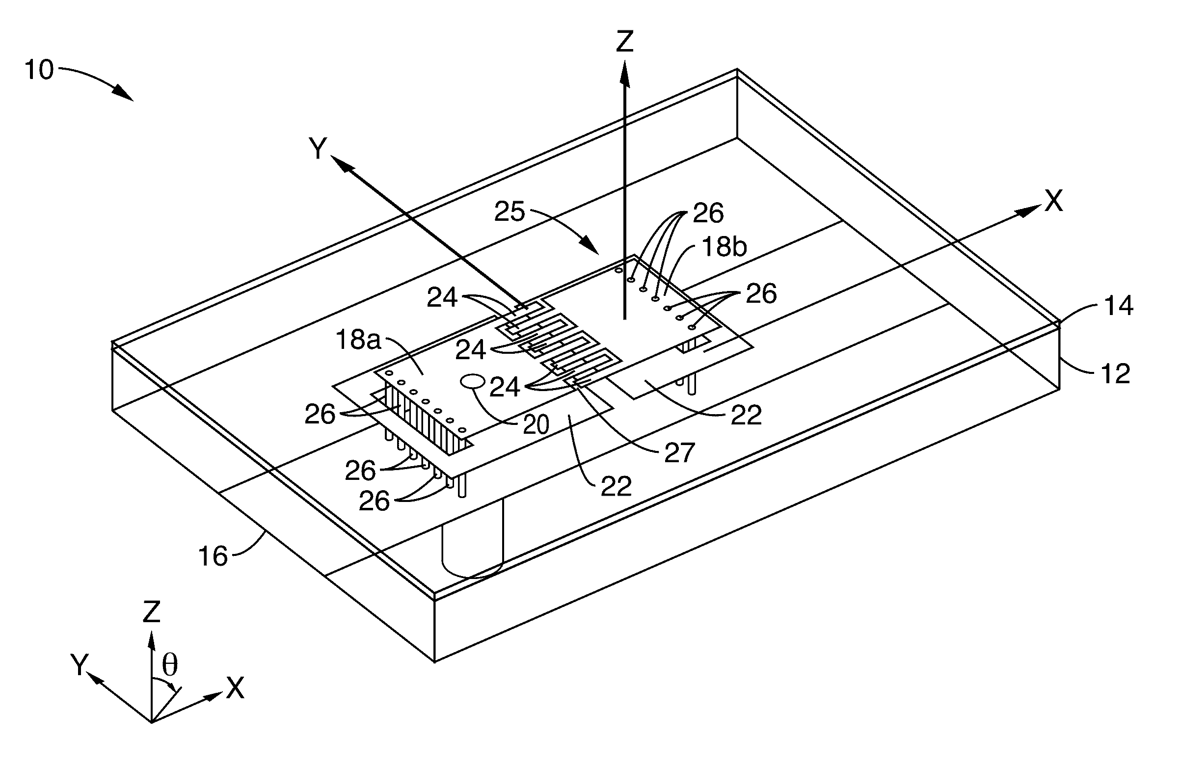
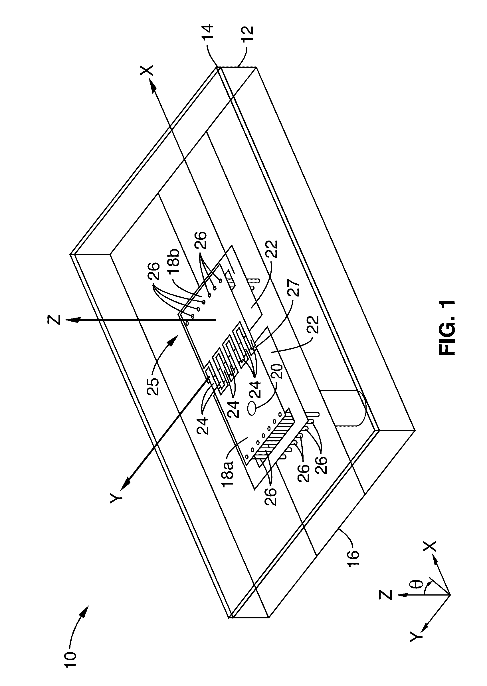
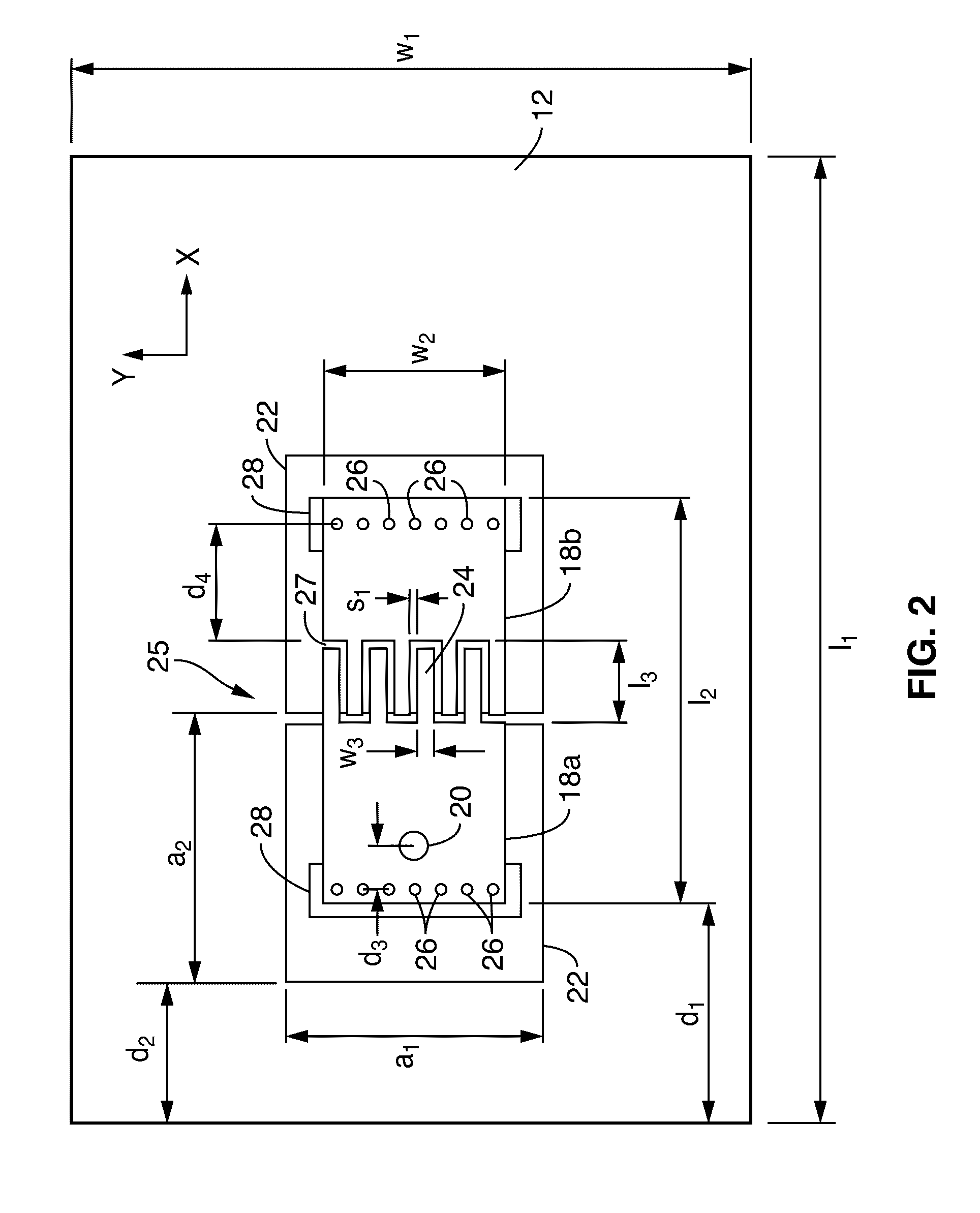
[0039]FIG. 1 shows a perspective view of the geometrical layout of an inductively-fed Vertical Split-Ring Resonator (VSRR) antenna 10 of the present invention. FIG. 2 shows a plan view of the geometrical layout, with dimensions, of the inductively-fed VSRR antenna 10 of FIG. 1. FIG. 3 shows a side view of the geometrical layout, of the inductively-fed VSRR antenna 10 of FIG. 1. An input comprising a coaxial feeding probe 20 is directly connected to the top surface 14 that forms the Split-Ring Resonator (SRR), which can be represented by a series inductor. The interdigitated capacitor 25, which is the split of the VSRR, is the main radiator of the antenna 10. The interdigitated capacitor 25 is split into first planar side 18a and second planar side 18b and interface via a series of parallel interdigitated fingers 24. The two ends first planar side 18a and second planar side 18b are shorted to the ground 16 (with vias 26), making the antenna 10 act as an open loop structure, which als...


PUM


Abstract

A vertical split ring resonator antenna is disclosed, comprising a substrate having an upper surface and lower surface, an interdigitated capacitor coupled to the upper surface of the substrate and ground coupled to the lower surface. The interdigitated capacitor includes a first planar segment and a second planar segment, each having interdigitated fingers that are separated by a gap disposed between the first planar segment and second planar segment. The interdigitated capacitor is coupled to the substrate to form a vertical split ring resonator.

Description

CROSS-REFERENCE TO RELATED APPLICATIONS[0001]This application is a 35 U.S.C. §111(a) continuation of PCT international application number PCT / US2012 / 043641 filed on Jun. 21, 2012, incorporated herein by reference in its entirety, which is a nonprovisional of U.S. provisional patent application Ser. No. 61 / 500,569 filed on Jun. 23, 2011, incorporated herein by reference in its entirety. Priority is claimed to each of the foregoing applications.[0002]The above-referenced PCT international application was published as PCT International Publication No. WO 2012 / 177946 on Dec. 27, 2012 and republished on Mar. 7, 2013, which publications are incorporated herein by reference in their entireties.STATEMENT REGARDING FEDERALLY SPONSORED RESEARCH OR DEVELOPMENT[0003]Not ApplicableINCORPORATION-BY-REFERENCE OF MATERIAL SUBMITTED IN A COMPUTER PROGRAM APPENDIX[0004]Not ApplicableNOTICE OF MATERIAL SUBJECT TO COPYRIGHT PROTECTION[0005]A portion of the material in this patent document is subject to...

Claims


Application Information

Patent Timeline
Patent Type & Authority Patents(United States)
IPC IPC(8): H01Q9/16H01Q1/22H01Q9/04H01Q7/00H01Q1/50
CPCH01Q1/50H01Q1/2266H01Q7/00H01Q9/0407H01Q9/0414H01Q9/0421H01Q9/0442H01Q9/16
Inventor ITOH, TATSUODONG, YUANDANTOYAO, HIROSHI
Owner NEC CORP
Why Eureka
Try Eureka