Mechanical cell lysis apparatus

a cell lysis and mechanical technology, applied in the field of cell lysis apparatuses, can solve the problems of degradation of cell proteins, requiring separate laser generators, deformation of cells, etc., and achieves the effects of facilitating cell lysis, rapid cell lysis and immediate analysis, and efficient cell disruption

Active Publication Date: 2016-11-29
RADIANQBIO CO LTD
View PDF15 Cites 3 Cited by
  • Summary
  • Abstract
  • Description
  • Claims
  • Application Information

AI Technical Summary

Benefits of technology

[0015]According to the present invention, the cell lysis apparatus may achieve efficient disruption of cells without cell degradation caused by application of thermal, electrical or chemical impact to the cells.
[0016]In addition, the cell lysis apparatus according to the present invention permits rapid cell lysis and immediate analysis of cell lysates. Further, the cell lysis apparatus according to the present invention may be directly connected to a manual type syringe, thereby facilitating cell lysis.
[0017]Furthermore, the cell lysis apparatus according to the present invention may be manufactured as a disposable cell lysis apparatus, thereby providing economic feasibility while reducing contamination due to reuse of the apparatus.

Problems solved by technology

As such, the optical cell lysis is carried out by radiating laser micropulses into a particular cell or to an adjacent region thereof, causing deformation of the cell and requiring a separate laser generator.
Cell disruption using ultrasound waves requires a long time and makes it difficult to obtain uniform energy distribution of the ultrasound waves, thereby providing inconsistent results.
However, these methods apply thermal impact to the cell, causing degradation of cell proteins.
However, such chemical cell lysis disadvantageously causes degradation of cell proteins, and requires separate reagents for cell lysis and removal of the reagents after the cell lysis, and a long time for cell lysis.
However, this apparatus entails high cost due to the silicon DRIE process.

Method used


Image

  • Mechanical cell lysis apparatus
  • Mechanical cell lysis apparatus
  • Mechanical cell lysis apparatus

Examples


Embodiment Construction

[0034]Exemplary embodiments of the present invention will now be described in detail with reference to the accompanying drawings. It should be noted that like components will be denoted by like reference numerals throughout the specification and the drawings. In addition, description of details apparent to those skilled in the art will be omitted for clarity. Further, it should be understood that the present invention is not limited to the following embodiments and may be embodied in different ways by those skilled in the art without departing from the scope of the present invention.

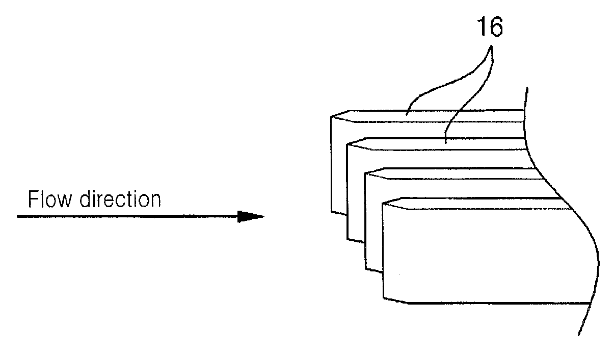
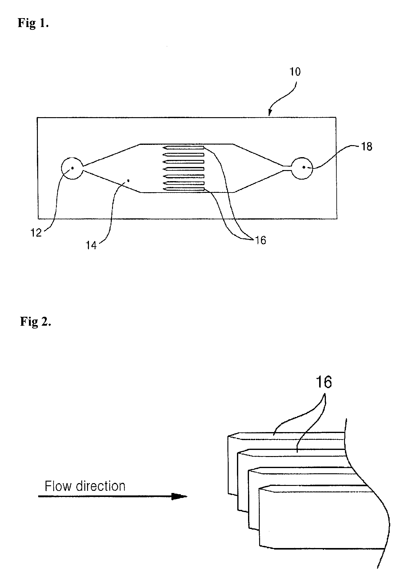
[0035]FIG. 1 is a plan view of a cell lysis apparatus in accordance with one exemplary embodiment of the present invention, and FIG. 2 is an enlarged perspective view of nano blades of the cell lysis apparatus in accordance with the exemplary embodiment of the present invention.

[0036]The cell lysis apparatus 10 according to one exemplary embodiment includes an inlet port 12, an outlet port 18, a fluid ch...


PUM

PropertyMeasurementUnit
distanceaaaaaaaaaa
widthaaaaaaaaaa
heightaaaaaaaaaa

Abstract

The present invention relates to a cell lysis apparatus and a manufacturing method thereof, and more particularly, to a cell lysis apparatus, which mechanically performs cell lysis, and a manufacturing method thereof. The cell lysis apparatus includes: an inlet port through which fluid containing cells is supplied; a fluid channel defining a passage through which the cell containing fluid supplied from the inlet port flows; a nano blade array including a plurality of nano blades having pointed leading ends and arranged such that the pointed leading ends of the nano blades are oriented in a direction of the fluid supplied through the inlet port to disrupt the cells passing therethrough; and an outlet port through which the disrupted cells and the fluid are discharged.

Description

TECHNICAL FIELD[0001]The present invention relates to a cell lysis apparatus and a manufacturing method thereof, and more particularly, to a cell lysis apparatus, which mechanically performs cell lysis, and a manufacturing method thereof.BACKGROUND ART[0002]Cell lysis refers to the process of decomposing a cell such that the membrane of the cell is disrupted and the intercellular components are exposed. Cell lysis is primarily performed in cell classification and protein purification. Cell lysis is generally carried out as an initial stage to separate DNA or RNA in a DNA or RNA amplification process such as PCR (Polymerase Chain Reaction).[0003]Cell lysis for cell disruption is generally classified into optical, mechanical, acoustic, electrical, and chemical cell lysis.[0004]In optical cell lysis, laser micropulses are radiated to a target cell to form a cavitation bubble such that the cell is disrupted through expansion of the cavitation bubble. As such, the optical cell lysis is c...

Claims


Application Information

Patent Timeline
Patent Type & Authority Patents(United States)
IPC IPC(8): B02C19/00C12M1/00
CPCC12M47/06B02C19/0056C12Q1/24G01N33/48
Inventor YANG, SUNGYUN, SUNG SIKYOON, SANG YOUL
Owner RADIANQBIO CO LTD
Why Eureka
Try Eureka