Unmanned aircraft system (UAS) with active energy harvesting and power management

Active Publication Date: 2016-12-27
ROLLEFSTAD SCOTT B
View PDF20 Cites 127 Cited by
  • Summary
  • Abstract
  • Description
  • Claims
  • Application Information

AI Technical Summary

Benefits of technology

[0006]Embodiments of the invention are directed to an aircraft energy harvesting and power management system comprising a battery-powered airframe having a plurality of powered and unpowered rotors; flight electronics systems for providing control and power to the powered rotors to sustain flight operations, the flight electronics systems controlling the unpowered rotors to modify plan surface area as required; and software comprising energy generation and plan surface area optimization functions for minimizing power consumption and/

Problems solved by technology

However, all known versions share an Achilles' heel:

Method used


Image

  • Unmanned aircraft system (UAS) with active energy harvesting and power management
  • Unmanned aircraft system (UAS) with active energy harvesting and power management
  • Unmanned aircraft system (UAS) with active energy harvesting and power management

Examples


first embodiment

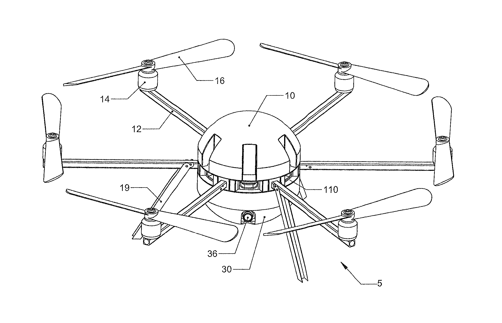
[0033]In the inventive principles underlying the various inventions herein the unpowered rotors are also referred to herein as “free-wheeling propellers” and are propellers connected to the arms with no connection to micro-generators or motors, and no electronic connection to the autopilot and electronic sensors—they are literally free-wheeling. In this embodiment the aircraft can extend its stationary (aka hovering) flight time by using natural wind, convection currents, and turbulence to harvest energy from these air currents to create lift much like an eagle does in gliding from thermal updraft to updraft, or a sailplane in riding thermals and ridge waves. In one embodiment eight propellers are used on the aircraft: four powered propellers for flying from point to point and stabilizing the aircraft, and four unpowered (free-wheeling) propellers for harvesting the energy from air currents. In one embodiment, the free-wheeling propellers are mounted to a bearing shaft and are free ...

third embodiment

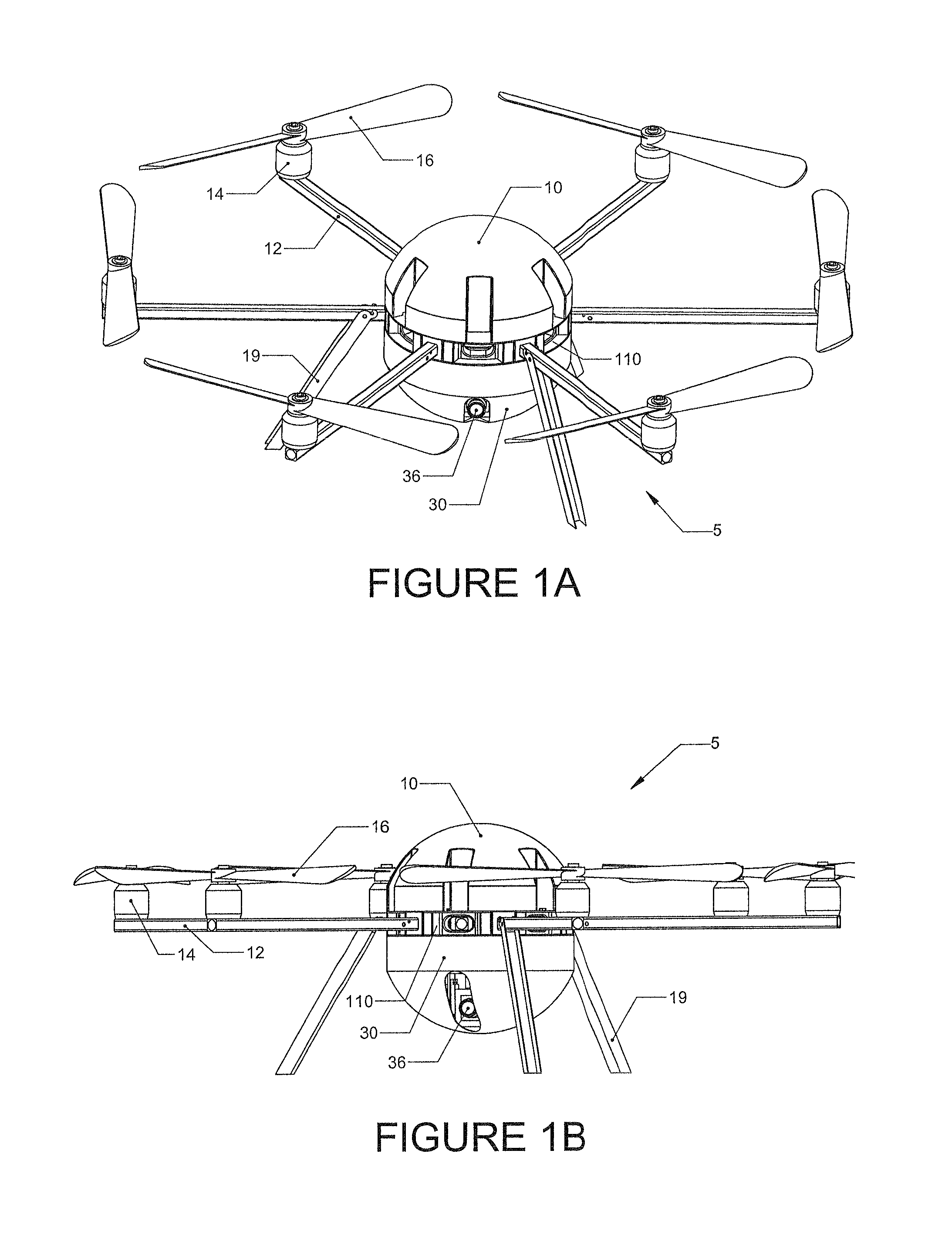
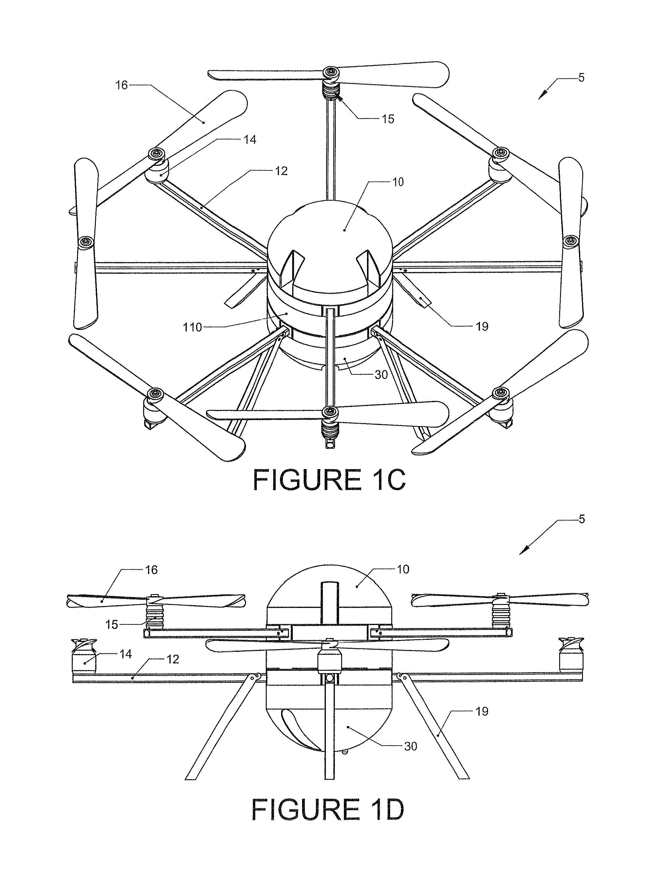
[0040]In a third embodiment the rotors may be stacked in layers of two or more parallel or nearly parallel planes. For example, FIG. 1A-1B shows an embodiment of the aircraft with six rotors arranged in a single plane in a spoke-and-hub arrangement. However, FIG. 1C-1D show an eight-rotor embodiment, with four rotors located on a first lower plane and connected to electric motors, and four more “free-wheeling” rotors located on a second parallel plane arranged above the first plane.

2. Defined Terms

[0041]The terms “free-wheeling propellers” and “unpowered rotors” are used interchangeably throughout this patent document. The terms “waypoint,”“destination” and “point of interest” are also used interchangeably. “Propeller” and “rotor” are also used interchangeably.

Aircraft Energy Harvesting and Power Management System

[0042]Embodiments of the invention are directed to an aircraft energy harvesting and power management system comprising a battery-powered airframe having a plurality of pow...


PUM


Abstract

A method of harvesting and managing energy from air currents, by small unmanned aircraft systems (UAS) having a plurality of powered and unpowered rotors, to increase the aircraft's flight time, especially where the mission requires extensive hovering and loitering, is provided. Conventional powered rotors create lift for the aircraft. Unpowered rotors can either be: 1) Free-wheeling rotors which increase the plan form area of aircraft as they rotate, increasing lift, and reducing the power draw on the battery, and/or 2) Rotors connected to micro-generators, which serve as a brake on the unpowered rotors, create electrical power to charge the aircraft batteries or directly power the aircraft's electronics. The invention's folding rotor arm design results in a compact package that is easily transported by a single user (man portable). The aircraft can be removed from its protective tube, unfolded and launched for flight in less than a minute. Extended flight times, compact easily transported design, and ability to host flight software on a user's tablet/PC result in low total cost of ownership.

Description

CROSS REFERENCE TO RELATED APPLICATION[0001]This application claims priority from U.S. Provisional Application Ser. No. 61 / 707,468, filed Sep. 28, 2012, the contents of which are incorporated herein by reference.BACKGROUND[0002]1. Field of the Invention[0003]The embodiments of the invention are directed to improvements in the design and operational efficiency of multi-rotor unmanned aircraft systems (UAS) specifically through the application of energy harvesting and power management strategies.[0004]2. Description of Related Art[0005]Wireless radio-controlled (R / C) model helicopters are well-known precursors to today's more sophisticated multi-rotor aircraft such as the Mikrokopter from Mikrokopter.de, or the ArduCopter 3DR-B from Udrones.com. Today's multi-rotor unmanned aircraft systems (UAS) can be manually operated by the user or flown autonomously (i.e., completely preprogrammed flight) or semi-autonomously, and can be purchased off-the-shelf, with 4, 6 or 8 rotors, GPS based g...

Claims


Application Information

Patent Timeline
IPC IPC(8): B64C39/02G05D1/00B64D41/00
CPCB64C39/024G05D1/0022G05D1/0088B64D41/00B64C2201/024B64C2201/066B64C2201/145B64C2201/146G05D1/0005Y02T50/50Y02T50/40B64U50/34B64U2201/104B64U10/10B64U30/20B64U50/19B64U2201/20
Inventor ROLLEFSTAD, SCOTT B.
Owner ROLLEFSTAD SCOTT B
Why Eureka
Try Eureka