Machine for machining pipe ends, having a centering device for centering a tubular workpiece in relation to an axis of rotation

Inactive Publication Date: 2017-01-03
SMS MEER
View PDF23 Cites 9 Cited by
  • Summary
  • Abstract
  • Description
  • Claims
  • Application Information

AI Technical Summary

Benefits of technology

[0010]The object of invention is therefore to create a pipe-end machining apparatus of the above-described type in which precise centering of the tubular workpie

Problems solved by technology

It is problematic, in this connection, that centering of the tubular workpiece is sometimes difficult.
Position deviations from the center of rotation, i.e. from the axis or the center of the machining apparatus, bring about corresponding production inaccuracies and unsatisf

Method used


Image

  • Machine for machining pipe ends, having a centering device for centering a tubular workpiece in relation to an axis of rotation
  • Machine for machining pipe ends, having a centering device for centering a tubular workpiece in relation to an axis of rotation
  • Machine for machining pipe ends, having a centering device for centering a tubular workpiece in relation to an axis of rotation

Examples


Embodiment Construction

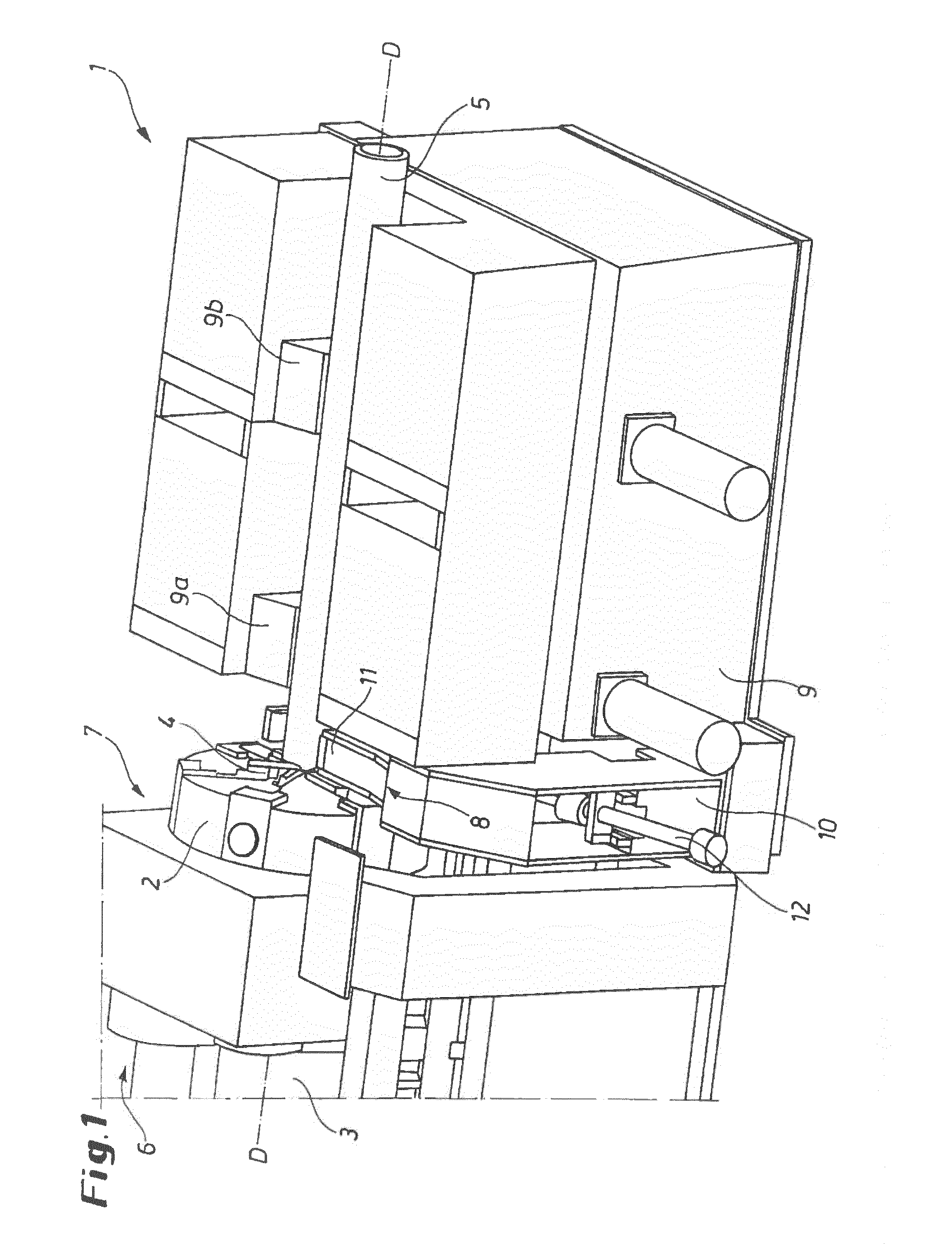
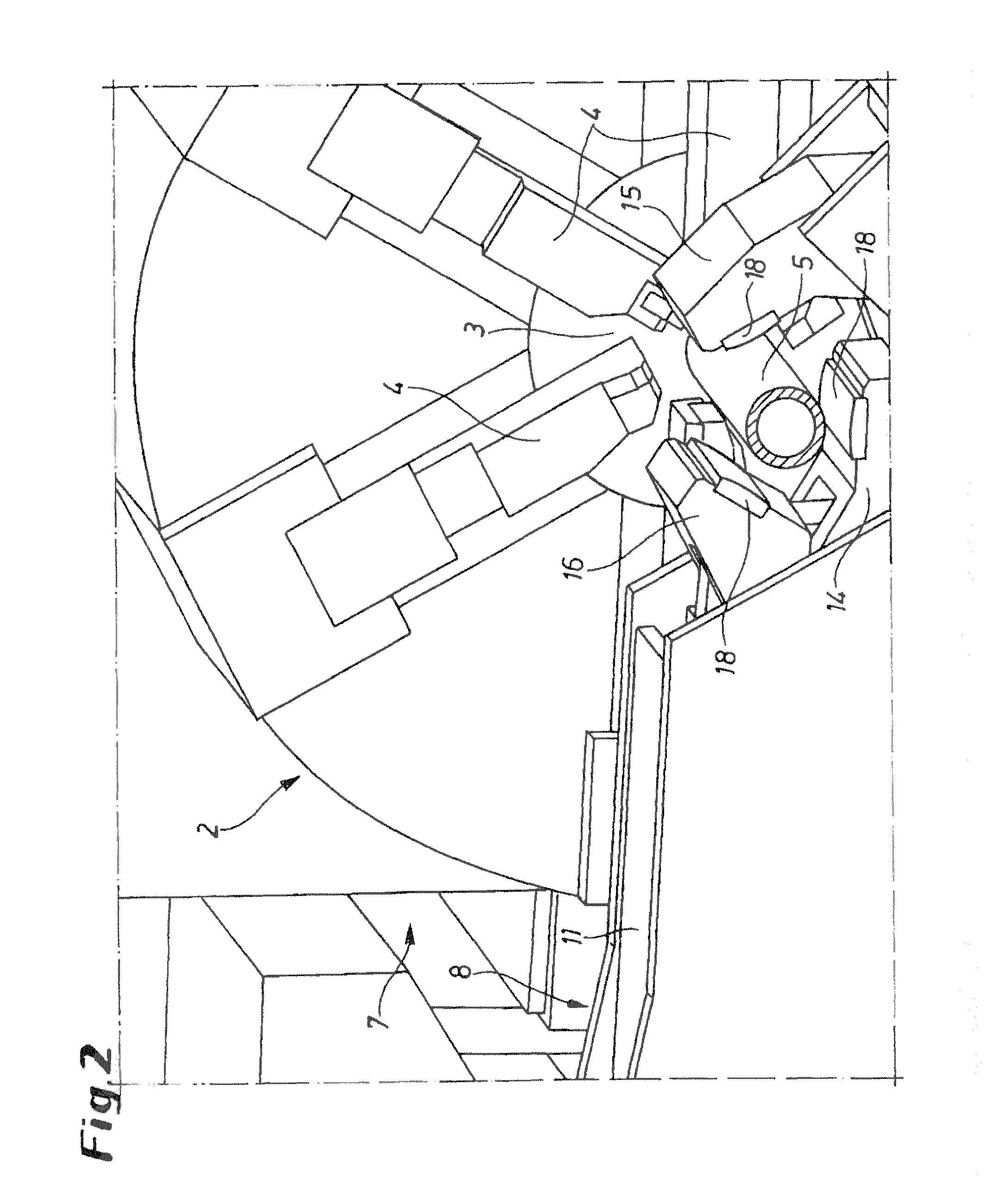
[0030]FIG. 1 shows an apparatus 1 for machining pipe ends that has a hollow main spindle 3 and a tool head 2 equipped with chip-removing machining tools 4, the spindle 3 and tool head 4 rotating about an axis D centered in the apparatus. An unillustrated drive is provided in a rear machine region 6 and a centering device 8 forward thereof and a clamp 9 further forward from the tool head 2 in a front machine region 7. The latter unit has multiple chucks 9a and 9b or the like, depending on the length of the workpiece 5.

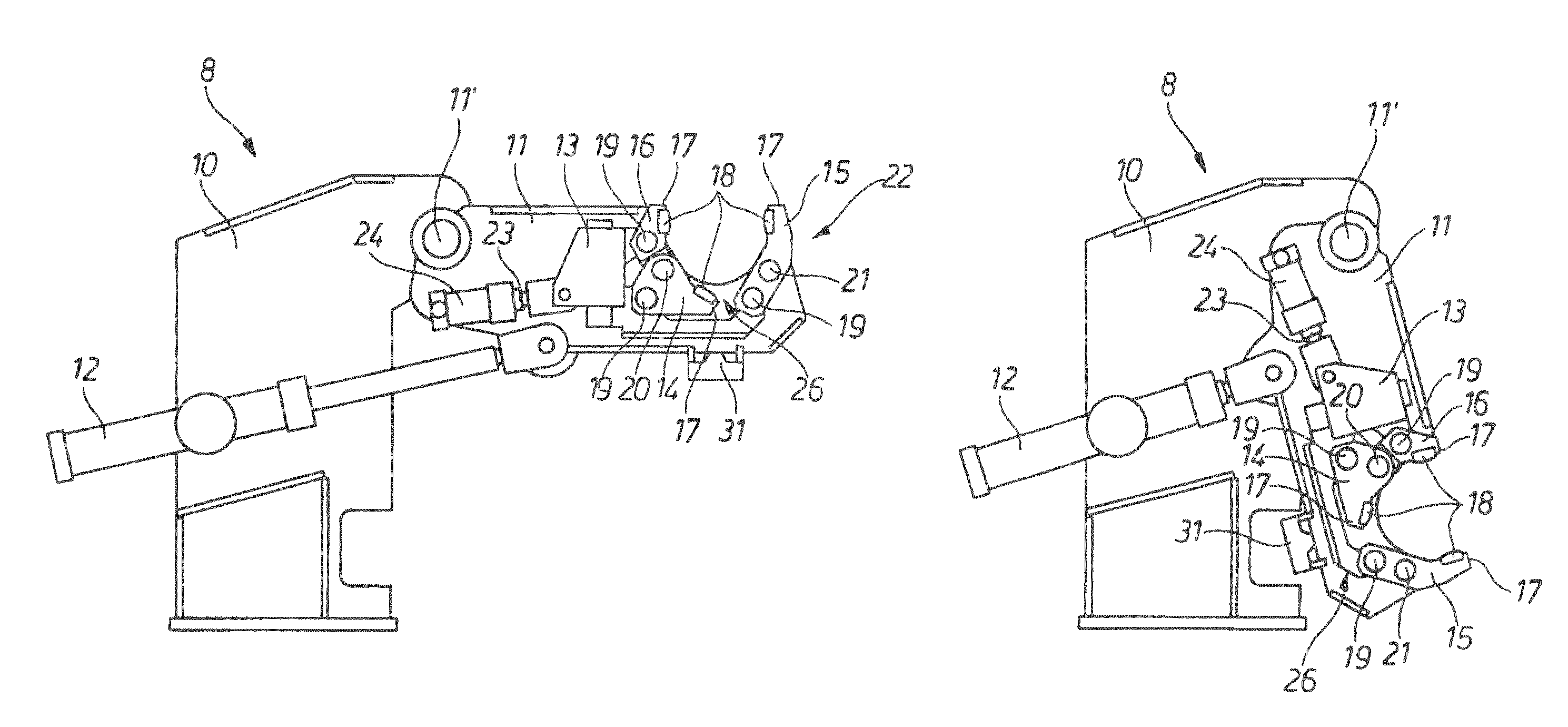
[0031]The centering device 8 comprises a portal-like stand 10 in which is mounted a pivot arm 11. The pivot arm 11 is connected with the portal-like stand 10 by a movably mounted piston / cylinder unit 12 for pivoting toward and away from the axis D about a rotation axis 11′ at the projecting end of the stand 10 (see FIGS. 3 and 4).

[0032]The pivot arm 11 carries an actuating body 13 associated with three levers 14, 15, and 16 whose free ends 17 carry jaws 18 for engaging ...


PUM


Abstract

The invention relates to a machine (1) for machining pipe ends. At least one centering device (8; 35) is associated to said machine, which centering device centers a tubular workpiece (5, 5′) in relation to an axis of rotation (D) of the machine for machining pipe ends extending in the center of the machine, the tubular workpiece either being stationary in the case of a rotating tool head (4) or rotating in the case in which the tubular workpiece is fastened in the machine chuck (9). Precise centering of the tubular workpiece (5, 5′) is quickly and simply achieved in that the centering device (8; 35) has a clamping housing (13; 130) that is open toward the axis of rotation (D), which clamping housing is designed comprising at least three means (14, 15, 16; 140, 150, 160) for contacting the tubular workpiece at the outer circumference and for clamping the tubular workpiece (5, 5′) in a centered manner, which means are circumferentially distributed and adjust mechanically independently of each other to the particular diameter of the workpiece (5, 5′) to be machined.

Description

CROSS REFERENCE TO RELATED APPLICATIONS[0001]This application is the US-national stage of PCT application PCT / EP2013 / 066053 filed 31 Jul. 2013 and claiming the priority of German patent application 102012015222.1 itself filed 31 Jul. 2012.FIELD OF THE INVENTION[0002]The invention relates to an apparatus for machining pipe ends having at least one device for centering on an axis at the center of the apparatus a tubular workpiece that is either rotating adjacent a stationary tool or stationary while the tool head orbits when gripped in the apparatus's chuck.[0003]In the state of the art, pipe-end machining machines or apparatuses are known that machine tubular workpieces. For this purpose, a machine spindle can be a hollow cylinder through which the pipe is pushed to the machining region of the pipe-end machining apparatus. There is a clamp on the apparatus that must grip and hold the tubular workpiece before the chip-removing machining process can take place.[0004]The tubular workpie...

Claims


Application Information

Patent Timeline
IPC IPC(8): B23B31/12B23B25/06B23B5/08B23Q1/76B23Q3/18B23Q3/06F16B2/10
CPCB23B25/06B23B5/08B23B31/1269B23B31/1276B23Q1/76B23Q3/183B23Q3/064F16B2/10Y10T82/2597B23B2270/12
Inventor ESSER, KARL-JOSEF
Owner SMS MEER
Why Eureka
Try Eureka