Coaxial loudspeaker arrangement

a loudspeaker and coaxial technology, applied in the direction of transducer details, transducer casings/cabinets/drawers, electrical transducers, etc., can solve the problems of short life time, increased distortion, and limited current load capacity of speaker systems with multiple speakers of that kind, so as to increase the sensitivity of the loudspeaker and the power output, the effect of increasing the magnetic field

Inactive Publication Date: 2017-01-03
MAGYAR INNOVACIOS SZOVETSEG
View PDF6 Cites 4 Cited by
  • Summary
  • Abstract
  • Description
  • Claims
  • Application Information

AI Technical Summary

Benefits of technology

[0010]Such a design ensures that the two voice coils will operate in magnetic fields of different strength, and the two magnets provide for both voice coils a magnetic field of sufficiently high strength. With increasing magnetic field, the sensitivity of the loudspeaker and the power output will be higher. The voice coils operating in magnetic fields of different strength will decrease the distortion of the loudspeaker even at a higher power output.
[0011]In one preferred embodiment, at least a part of the inner magnet and at least a part of the outer magnet is located in the same plane. This configuration enables the reduction of the size of the loudspeaker. Further, in this configuration, the upper plane surface of the inner magnet is located preferably in proximity of the upper plane surface of the outer magnet, above the upper plane surface of the outer magnet, and the lower plane surface of the inner magnet is located between the upper plane surface and the lower plane surface of the outer magnet.
[0020]In a further preferred embodiment of the invention, at least one of the voice coils has multiple layers, wherein the number of layers above each other is variable along the coil. In a preferred embodiment, the voice coil has a conical shape in cross section, with more windings above each other on the diaphragm side, and less windings on the other side opposite the diaphragm. Such a configuration may contribute to a substantial reduction of the unpleasant audio effect, generally known from conventional loudspeakers, which is produced when a driving power amplifier is connected or the level of the audio frequency signal changes to a great extent.

Problems solved by technology

Generally, speaker systems with multiple speakers of that kind can only be mounted into relatively large speaker boxes.
Due to the smaller size, the loudspeakers with coaxial configuration have less power output, e.g. the current load capacity is more limited when compared to multi-speaker systems of larger size.
Higher voltage- or current load in such conventional multi-speaker systems will lead to higher distortion and shorter life time.
The loudspeaker is small in size and weight, but it is not suitable to provide higher power audio output.
A further problem arises from the fact that both of the diaphragm voice coils move in a magnetic field of substantially the same strength, which, without appropriate frequency dependent compensation, would cause distortion.
These solutions provide for the possibility to control the different voice coils in magnetic fields of different strength, but the arrangement of the two diaphragms in two planes above each other leads to a difficult construction and to a higher weight.

Method used


Image

  • Coaxial loudspeaker arrangement
  • Coaxial loudspeaker arrangement
  • Coaxial loudspeaker arrangement

Examples


Embodiment Construction

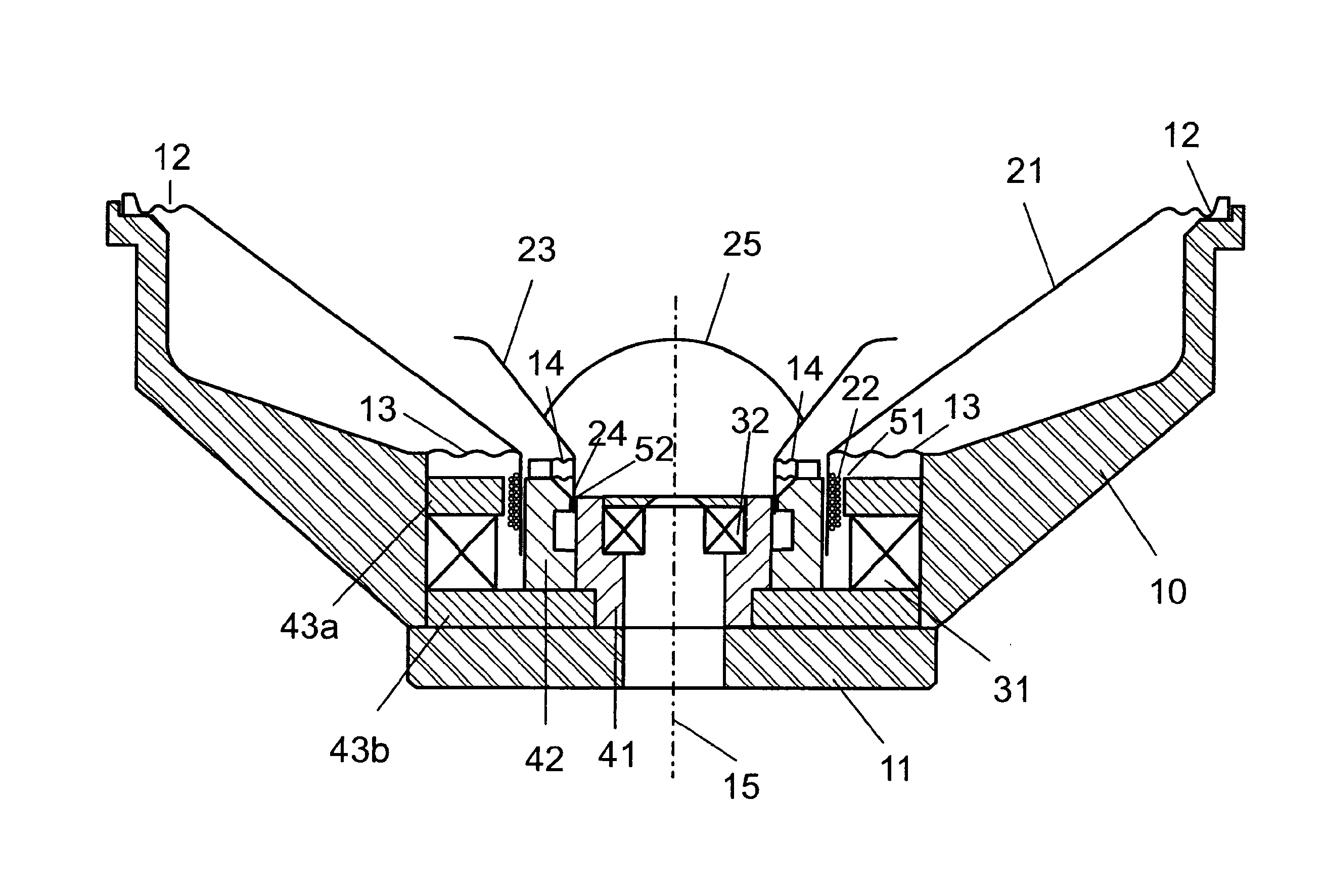
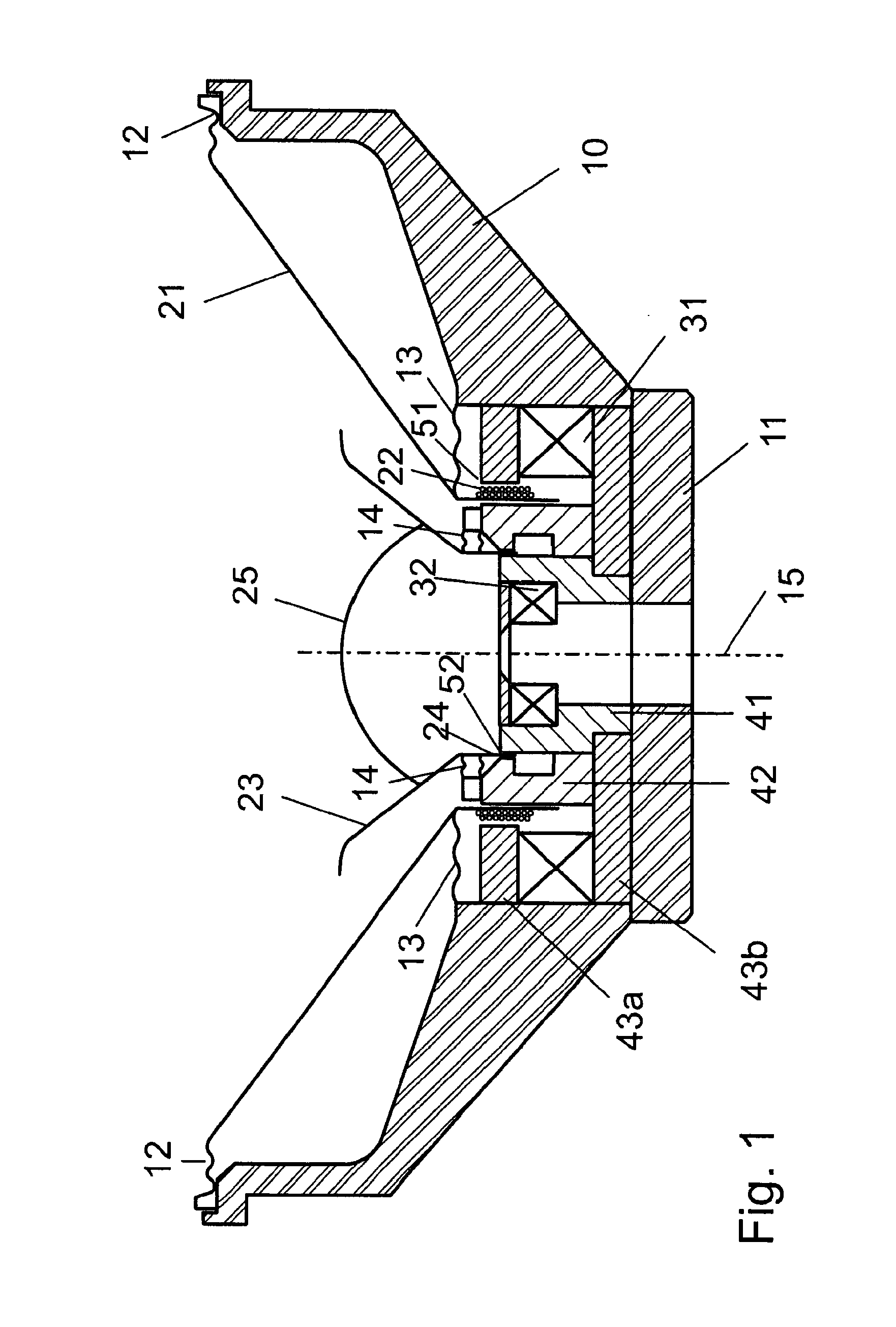
[0027]In FIG. 1, a coaxial loudspeaker arrangement according to the present invention is shown in a lateral cross-sectional view. As it can be seen, the coaxial loudspeaker arrangement has a common loudspeaker frame 10 with a disc shaped base plate 11, with radially extending ribs which are connected and terminated by a circular rim. The loudspeaker frame is basically non magnetic, and thus can be prepared from a plastic material. In order to withstand higher strain and power, it may be preferably made of a non magnetic metal, advantageously of aluminium or an aluminium alloy. A loudspeaker frame of metal, such as aluminium is also suitable for heat transfer.

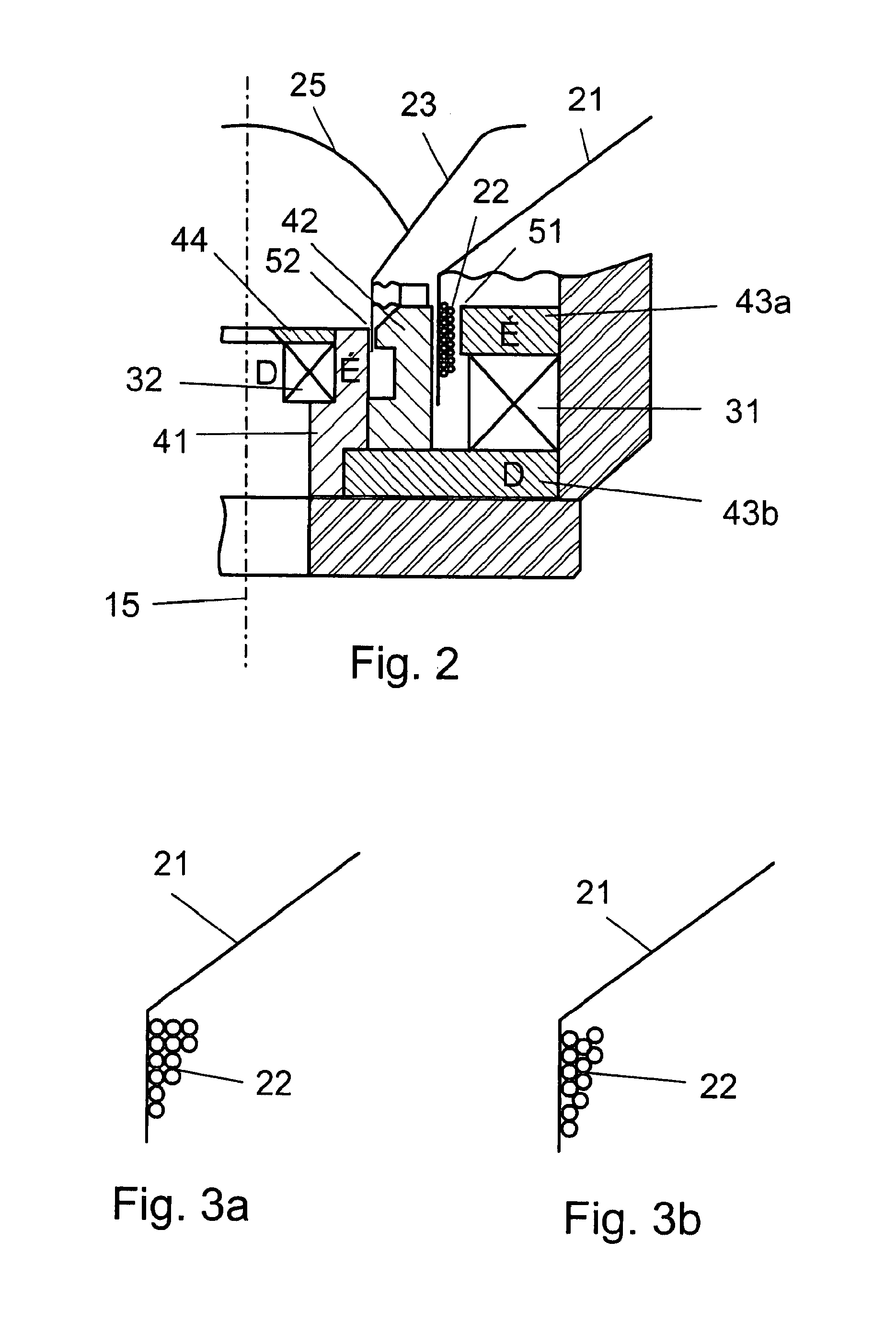
[0028]An outer diaphragm 21 operating in a lower frequency band and provided with an outer voice coil 22 is secured to the circular upper rim and a circular lower rim through flexible suspension elements (spider) 12 and 13. An inner diaphragm 23 provided with an inner voice coil 24 and operating in a higher frequency band is arr...


PUM


Abstract

Coaxial loudspeaker arrangement with an outer diaphragm (21) for operating in a lower frequency range, an inner diaphragm (23) for operating in a higher frequency range, both located in a common loudspeaker frame (10), with an outer voice coil (22) connected to the outer diaphragm (21), an inner voice coil (24) connected to the inner diaphragm (23), two coaxially arranged magnets (31, 32), and ferrite cores (41, 42, 43) in association with the magnets, wherein the voice coils (22, 24) extend into air gaps (51, 52) between the ferrite cores, and the diaphragms are connected to the loudspeaker frame (10) through flexible suspending elements (11-14). In the proposed loudspeaker, an inner core (41) and an outer core (42) separated from each other by an inner air gap (52), is located between an outer magnet (31) and an inner magnet (32); one ferrite core (43a) of the outer magnet (31) is separated by an outer air gap (51) from the outer core (42) located between the two magnets, wherein the voice coil (22) of the outer diaphragm (21) extends into the outer air gap (51) and the voice coil (24) of the inner diaphragm (23) extends into the inner air gap (52).

Description

CROSS-REFERENCE TO RELATED APPLICATION[0001]The present application is a National Stage of International Application No. PCT / HU2013 / 000094, filed Sep. 16, 2013, which claims priority to HU P1200534, filed Sep. 17, 2012, the entire disclosures of which are hereby expressly incorporated herein by reference.TECHNICAL FIELD[0002]The present invention relates to a coaxial loudspeaker arrangement with an outer diaphragm for operating in a lower frequency range, an inner diaphragm for operating in a higher frequency range, both located in a common loudspeaker frame, with an outer voice coil connected to the outer diaphragm, an inner voice coil connected to the inner diaphragm, two coaxially arranged magnets, and ferrite cores in association with the magnets, wherein the voice coils extend into air gaps between the ferrite cores, and the diaphragms are connected to the loudspeaker frame through flexible suspending elements.BACKGROUND ART[0003]Loudspeakers as electro-acoustic converters, are...

Claims


Application Information

Patent Timeline
Patent Type & Authority Patents(United States)
IPC IPC(8): H04R25/00H04R7/16H04R9/04H04R7/02H04R1/24H05K5/00H04R1/40H04R1/00
CPCH04R7/16H04R7/02H04R9/04H04R1/24H04R1/403H04R9/025H04R9/046
Inventor PAPP, GERGELY
Owner MAGYAR INNOVACIOS SZOVETSEG
Why Eureka
Try Eureka