
Quantum imaging with undetected photons

a quantum imaging and photon counter technology, applied in the field ofquantum imaging and quantum spectroscopy, can solve the problems of major drawback, high dark count of mir photon counters, and difficulty in detecting the photons that illuminate objects

Active Publication Date: 2017-01-31
UNIVERSITY OF VIENNA +1
View PDF5 Cites 5 Cited by
  • Summary
  • Abstract
  • Description
  • Claims
  • Application Information

AI Technical Summary

Benefits of technology

This approach enables flexible wavelength selection for imaging and spectroscopy, reduces the need for intense light sources, and allows for imaging of sensitive samples without damage, with nearly 100% efficiency and the use of standard detectors, enhancing applications in various fields including medical imaging and cultural heritage conservation.

Problems solved by technology

However, detecting the photons that illuminate the object may be problematic.
For some applications, this requirement proves to be a major drawback of this imaging technique because there are not always detectors available at the wavelength necessary for the illumination of the object.
The problem with using triggered cameras is that the detection of the signal photons on the camera must be triggered by the detection of its brother idler photon.
This is a major drawback.
However, MIR photon counters usually have high dark counts, such that these are not easy to use to trigger a camera.
However this technique is rather complicated.
This may be difficult to provide, especially when it comes to sources at non-visible wavelengths, of which only few are available.
Moreover, this technique relies on a stimulated nonlinear process and therefore requires intense light beams.
However, there may be many application areas such as imaging or studying fragile samples, e.g. biological samples, paintings etc. for which using intense light beams may not be needed or rather not wanted, since the high intensity would damage the sample.
Such MIR cameras may be very demanding—a commonly used technical approach is based on cryogenic InSb semiconductor technology, cf.
MIR cameras are expensive and the InSb semiconductor technology inside needs to be cooled down to very low temperatures.
However, these cameras still feature a lot of noise and often exhibit poor signal-to-noise ratios.
Due to the requirement of strong pump lasers, in order to be efficient, using this technique for many applications is hampered if not impossible.

Method used


Image

  • Quantum imaging with undetected photons
  • Quantum imaging with undetected photons
  • Quantum imaging with undetected photons

Examples


examples

[0098]The following should provide proof of principle results, using the above-described embodiments.

[0099]In FIG. 6 a first example is shown. For this example, two periodically poled potassium titanyl phosphate, ppKTP, crystals are used as non-linear media. It should be noted that bulk crystals could be used as well. The sample is a silicon sample. The sample has a figure, i.e., a symbolic cat-like outline, etched on the sample. The source beam is a 532 nm pump laser. The sample is then illuminated with 1550 nm photons. This may be regarded as a telecom wavelength. Cameras available at this wavelength are usually very expensive and exhibit lower performance than in the visible light spectrum. Moreover, such cameras may be subject to severe export restrictions. The image, however, is generated by using 810 nm photons impinging on the image generator. These photons with a wavelength of 810 nm do not interact with the sample.

[0100]It should be noted that silicon is basically opaque fo...


PUM

PropertyMeasurementUnit
FWHMaaaaaaaaaa
wavelengthaaaaaaaaaa

Abstract

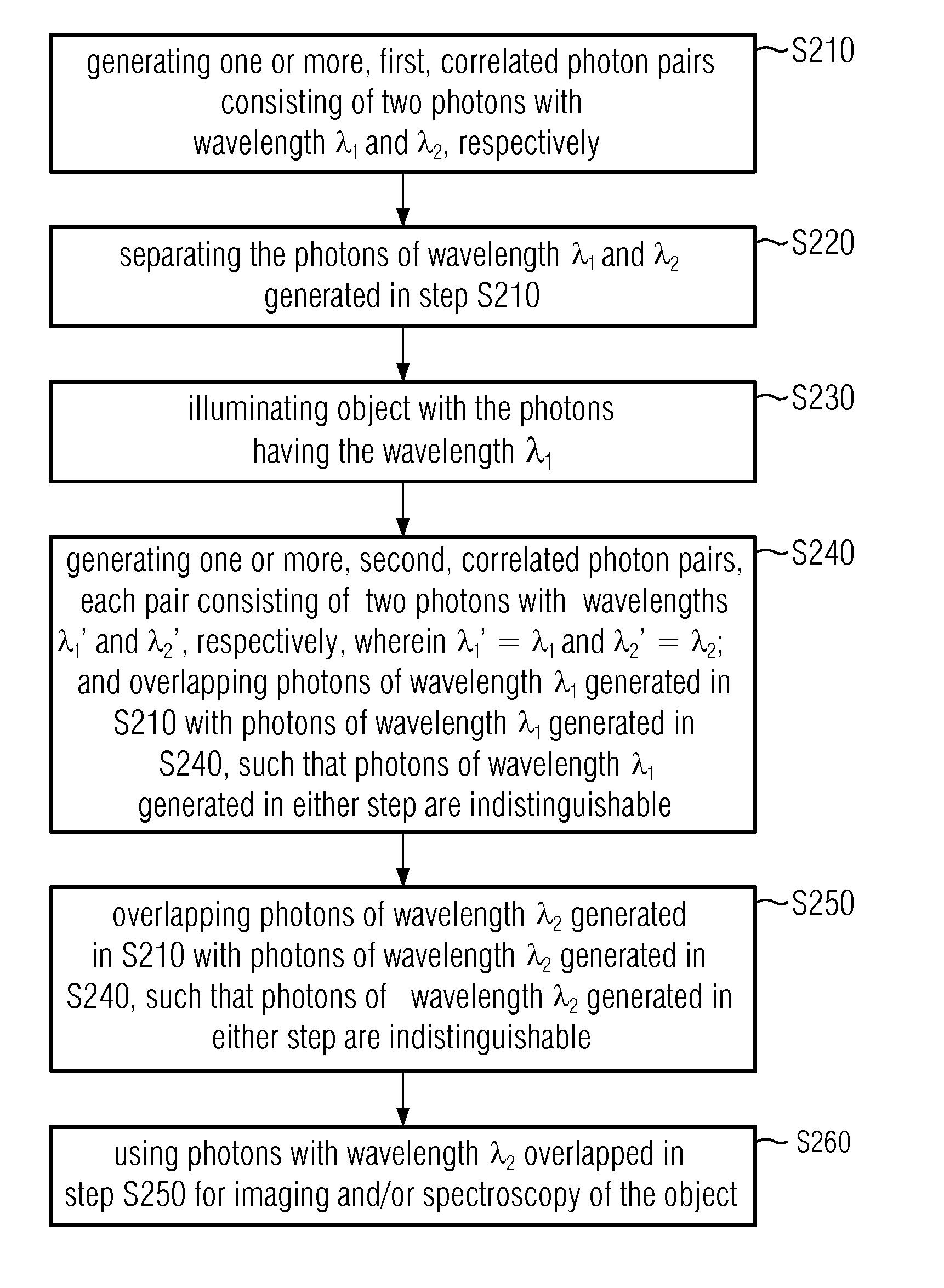
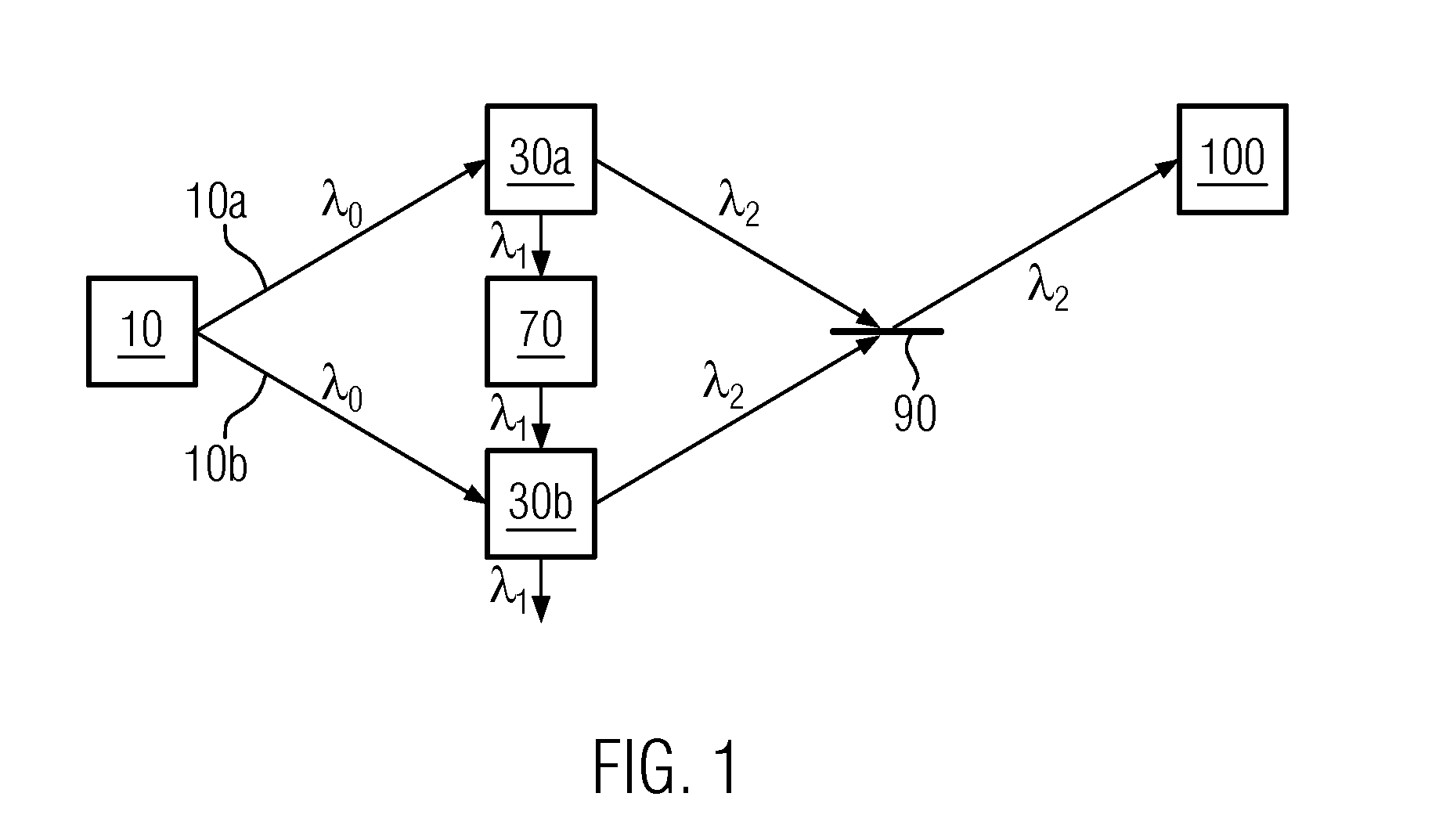
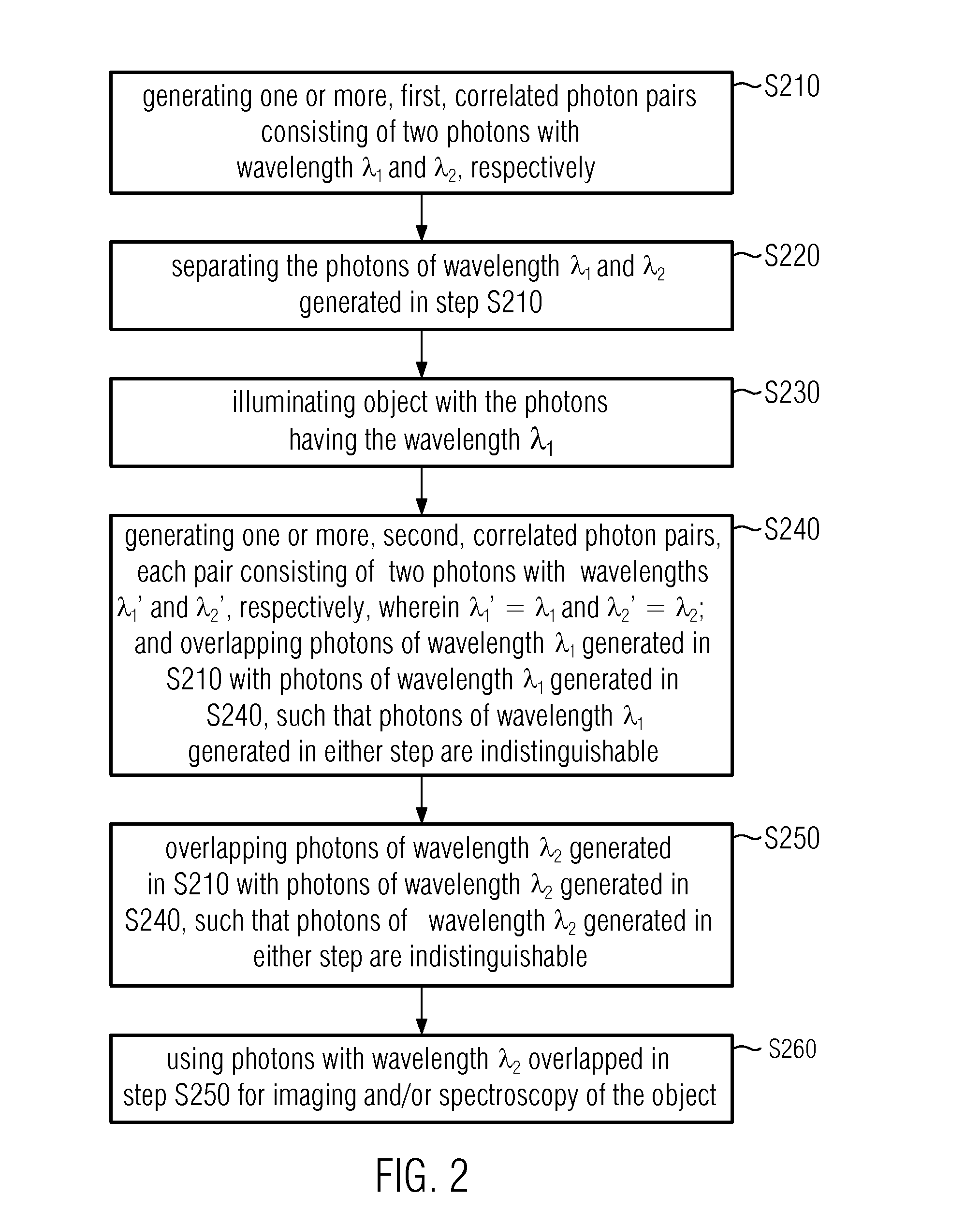
A method comprises: generating a first and a second correlated photon beam with wavelengths λ1 and λ2, respectively, wherein preferably λ1≠λ2; separating the first photon beam and the second photon beam; illuminating an object with the first photon beam; generating a third and a fourth correlated photon beam with wavelength λ1 and wavelength λ2, respectively; overlapping the first photon beam with the third photon beam such that photons of wavelength λ1 in either photon beam are indistinguishable; overlapping the second photon beam with the fourth photon beam such that photons of wavelength λ2 in either photon beam are indistinguishable; and using the overlapped photons of wavelength λ2 for imaging and / or spectroscopy of the object such that the photons that illuminate the object are not detected.

Description

CROSS REFERENCE TO RELATED APPLICATIONS[0001]The present application claims priority to European Patent Application No. 13198550.9, entitled “QUANTUM IMAGING WITH UNDETECTED PHOTONS,” filed on Dec. 19, 2013, the entire contents of which are hereby incorporated by reference for all purposes.FIELD OF THE INVENTION[0002]The present invention relates to the field of imaging using correlated photons, in particular quantum imaging, and quantum spectroscopy.BACKGROUND OF THE INVENTION[0003]When a laser beam, called a pump laser beam, is transmitted through a non-linear crystal, due to the interaction between the laser light and the crystal, there exists some probability that a pump laser photon, with angular frequency ω0, is annihilated giving rise to a photon pair with different angular frequencies. The angular frequency ω is connected to the (ordinary) frequency ν by ω=2πν. In the following, the term frequency will also be used for the angular frequency ω. Moreover, the angular frequency...

Claims


Application Information

Patent Timeline
Patent Type & Authority Patents(United States)
IPC IPC(8): G01N21/35G01N21/63G01N21/64G02F1/39G01N21/47
CPCG01N21/35G01N21/636G01N21/64G02F1/39G01N21/4795G01N2201/0686G01N2201/06113
Inventor ZEILINGER, ANTONRAMELOW, SVENLAPKIEWICZ, RADEKBORISH, VICTORIABARRETO LEMOS, GABRIELA
Owner UNIVERSITY OF VIENNA
Learn More