
Methods and systems for customizing cochlear implant stimulation and applications of same

a cochlear implant and customization technology, applied in the field of image processing, can solve the problems of reducing spectral resolution, challenging, and limited spectral resolution

Active Publication Date: 2017-02-21
VANDERBILT UNIV
View PDF9 Cites 3 Cited by
  • Summary
  • Abstract
  • Description
  • Claims
  • Application Information

AI Technical Summary

Benefits of technology

The patent describes a method and system for identifying the positions of cochlear implant electrodes and the nerves they stimulate for patient-specific programming. This approach uses a statistical shape model to estimate the location of the spiral ganglion, which is difficult to locate in imaging. The invention can provide useful data to improve speech recognition and overall outcomes for cochlear implant users.

Problems solved by technology

This is due, in part, to several well-known issues with electrical stimulation that prevent CIs from accurately simulating natural acoustic hearing.
Electrode interaction is an example of one such issue that, despite significant improvements made by advances in hardware and signal processing, remains challenging [4, 5].
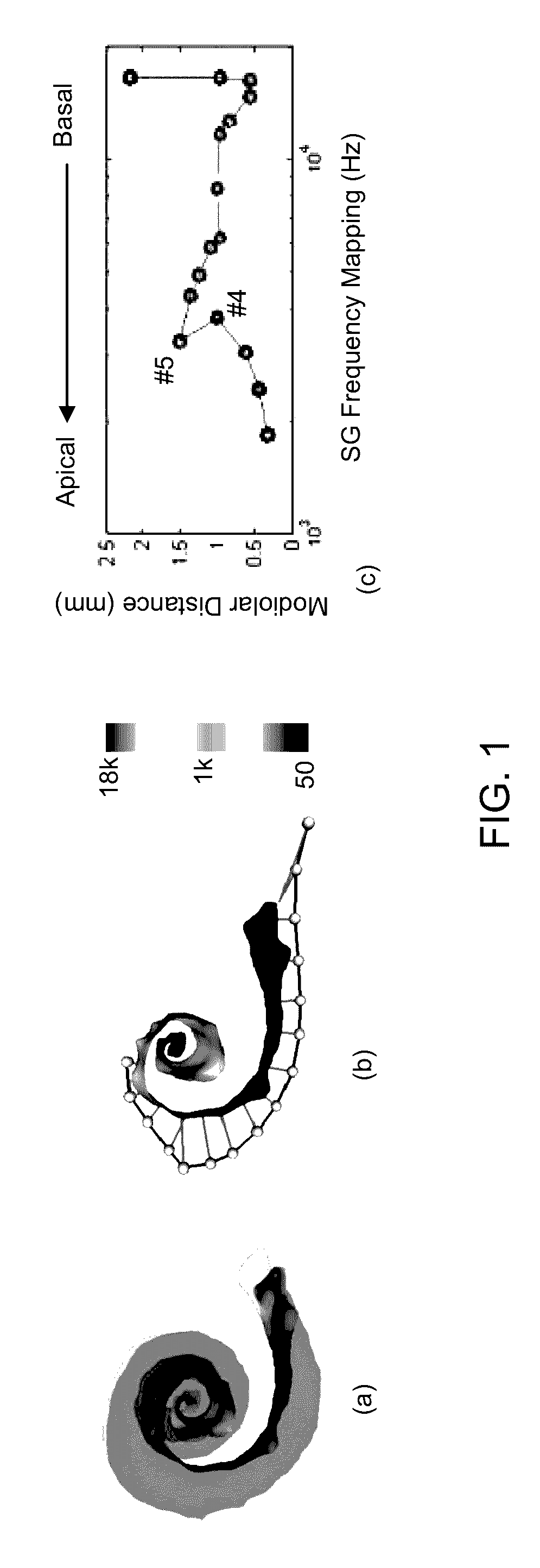
(1) The depth of the implanted array typically falls short of the apical position corresponding to the lowest perceived frequencies. Thus, the lowest frequency nerves are not stimulated, and a frequency shifting artifact is introduced, i.e., each electrode stimulates nerves that correspond to higher frequencies than the ones of the detected sound.
(2) Using the small number of electrodes in the CI array (i.e., 12 to 22) and due to their large size relative to individual nerves, limited spectral resolution is achievable, i.e., an electrode cannot target individual nerves, but rather stimulates nerves corresponding to a wide range of frequencies.
(3) Individual electrodes are positioned at variable depths and perimodiolar distances. Moreover, there has been no technology developed that allows accurate assessment of electrode position relative to stimulation targets in vivo. Depth discrepancies result in a frequency shift artifact. A larger distance to the SG leads to wider current spread from each electrode, further decreasing the spectral resolution.
Therefore, a heretofore unaddressed need exists in the art to address the aforementioned deficiencies and inadequacies.

Method used


Image

  • Methods and systems for customizing cochlear implant stimulation and applications of same
  • Methods and systems for customizing cochlear implant stimulation and applications of same
  • Methods and systems for customizing cochlear implant stimulation and applications of same

Examples


Embodiment Construction

[0091]The invention will now be described more fully hereinafter with reference to the accompanying drawings, in which exemplary embodiments of the invention are shown. This invention may, however, be embodied in many different forms and should not be construed as limited to the embodiments set forth herein. Rather, these embodiments are provided so that this disclosure will be thorough and complete, and will fully convey the scope of the invention to those skilled in the art. Like reference numerals refer to like elements throughout.

[0092]The terms used in this specification generally have their ordinary meanings in the art, within the context of the invention, and in the specific context where each term is used. Certain terms that are used to describe the invention are discussed below, or elsewhere in the specification, to provide additional guidance to the practitioner regarding the description of the invention. For convenience, certain terms may be highlighted, for example using...


PUM


Abstract

One aspect of the invention provides a method for customizing cochlear implant stimulation of a living subject. The cochlear implant includes an electrode array having a plurality of electrodes implanted in a cochlea of the living subject. The method includes determining a position for each of the plurality of electrodes and spiral ganglion nerves that the electrode array stimulates, determining a geometric relationship between neural pathways within the cochlea and the electrode array implanted therein, and using one or more electrodes of the electrode array to stimulate a group of SG neural pathways of the cochlea based on the location of the one or more electrodes and their geometric relationship with the neural pathways.

Description

CROSS-REFERENCE TO RELATED PATENT APPLICATIONS[0001]This application is a U.S. national phase application, under 35 U.S.C. §371, of PCT Patent Application Serial No. PCT / US2013 / 035076, filed Apr. 3, 2013, which itself claims priority to and the benefit of, pursuant to 35 U.S.C. §119(e), U.S. provisional patent application Ser. No. 61 / 619,824, filed on Apr. 3, 2012, entitled “SYSTEM AND METHODS OF COCHLEAR IMPLANT MAPPING BASED ON INTRACOCHLEAR POSITION OF ELECTRODE ARRAYS AND APPLICATIONS OF SAME”, by Jack H. Noble et al., which is incorporated herein in its entirety by reference.[0002]Some references, which may include patents, patent applications, and various publications, are cited and discussed in the description of this invention. The citation and / or discussion of such references is provided merely to clarify the description of the invention and is not an admission that any such reference is “prior art” to the invention described herein. All references cited and discussed in th...

Claims


Application Information

Patent Timeline
Patent Type & Authority Patents(United States)
IPC IPC(8): A61N1/36G06T7/00A61B5/00A61B5/12H04R25/00A61B6/00A61B6/03G06F19/00A61N1/05
CPCA61N1/36032A61B5/12A61B5/4893A61N1/36185G06T7/12G06T7/30G06T7/149H04R25/50H04R25/606A61B6/032A61B6/501A61B6/5235A61B2034/104A61B2034/105A61N1/0541G06F19/3437G06T2207/10081G06T2207/20124G06T2207/20128G06T2207/30052A61N1/36038A61N1/36039G16H50/50A61B34/10G06T7/337G06T7/74
Inventor NOBLE, JACK H.GIFFORD, RENE H.LABADIE, ROBERT F.DAWANT, BENOIT M.
Owner VANDERBILT UNIV
Learn More